Mitsubishi Montero (2004+). Manual - part 483
GENERAL DESCRIPTION
TSB Revision
WHEEL AND TIRE
31-3
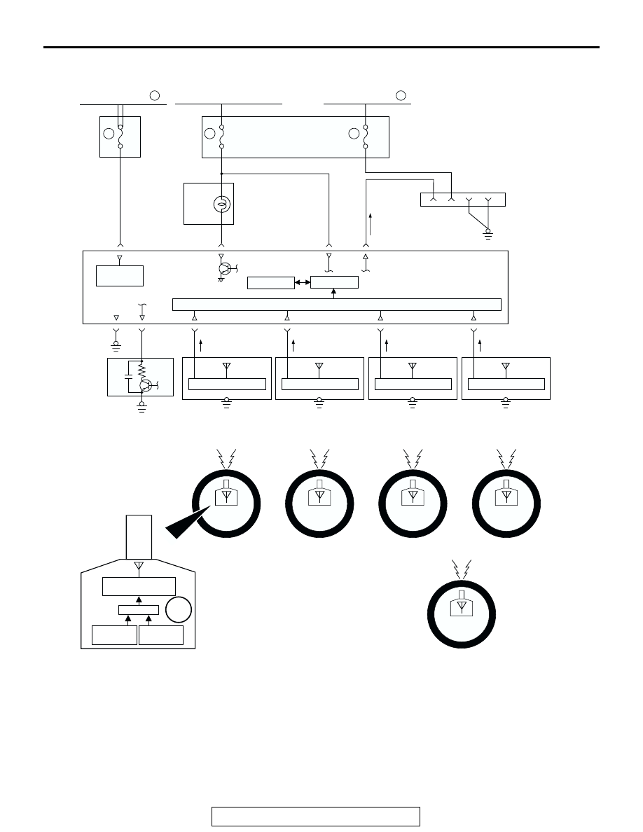
CIRCUIT DIAGRAM
• The TPMS receiver processes input signals from
each TPMS transmitter as well as vehicle speed
signals from the vehicle speed sensor. When the
road tire pressure is low, it sends a warning sig-
nal causing the TPMS warning light to be illumi-
nated. When the TPMS has problems, it sends a
warning signal causing the TPMS warning light to
be flashed.
• The TPMS transmitter includes a roll switch that
senses tire rotation. The TPMS receiver can
determine which tires are rotating (road tire) and
stationary (spare tire).
• For 3 seconds after the ignition switch is turned to
the "ON" position, the TPMS receiver illuminates
the TPMS warning light to check any breaks in
the TPMS warning light circuit.
AC307586
RELAY
BOX
JUNCTION
BLOCK
COMBINATION
METER
TPMS
RECEIVER
DATA LINK
CONNECTOR
FRONT TIRE (LH)
FRONT TIRE (RH)
REAR TIRE (LH)
REAR TIRE (RH)
IGNITION SWITCH (IG1)
FUSIBLE LINK
TPMS
POWER
SUPPLY
GND
RECEIVING CIRCUIT
EEPROM
VEHICLE
SPEED
SENSOR
CPU
TPMS TRANSMITTER
TPMS ANTENNA
(FRONT: LH)
CONTROL CIRCUIT
TPMS ANTENNA
(FRONT: RH)
CONTROL CIRCUIT
TPMS ANTENNA
(REAR: LH)
CONTROL CIRCUIT
CPU
TRANSMISSION
CIRCUIT
SPARE TIRE
18
15A
6
10A
10
20A
2
FUSIBLE LINK
1
AB
ANTENNA
TPMS ANTENNA
(REAR: RH)
CONTROL CIRCUIT
PRESSURE
SENSOR
ROLL
SWITCH
BATTERY