Mitsubishi Montero (2004+). Manual - part 468


  Index      Mitsubishi     Mitsubishi Montero - service repair manual 2004 year


Search            


Content   ..  466  467  468  469   ..


Mitsubishi Montero (2004+). Manual - part 468


REAR AXLE DIAGNOSIS

TSB Revision

REAR AXLE

27-11

STEP 2. Check for excessive gear backlash. Refer to 
GROUP 26, Differential Carrier 

 Inspection before 

Disassembly 

P.26-43

.

Q: Is the gear backlash correct?

YES : Go to Step 3.
NO :  Adjust the backlash. Then go to step 3.

STEP 3. Retest the system.
Q: Is the heat eliminated?

YES : The procedure is complete.
NO :  Start over at Step 1.

INSPECTION PROCEDURE 9: Oil Leakage <DIFFERENTIAL>

DIAGNOSIS

STEP 1. Check the breather hose for clogging.
Q: Is the breather hose clogged?

YES : Clean or replace the part. Then go to Step 5.
NO :  Go to step 2.

STEP 2. Check the cover installation.
Q: Is the cover installed correctly?

YES : Go to Step 3.
NO :  Repair. Then go to Step 5.

STEP 3. Check the oil seal for wear or damage.
Q: Is the oil seal worn or damaged?

YES : Replace the seal. Then go to Step 5.
NO :  Go to Step 4.

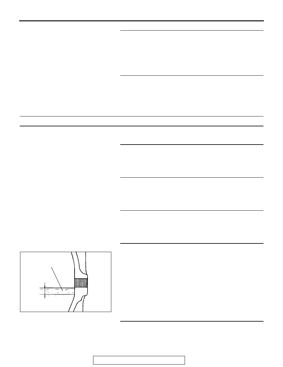
STEP 4. Check the oil level.

Remove the filler plug and check the gear oil level.
Q: Is the gear oil level more than 5 mm (0.2 inch) below the 

bottom of the filler plug hole?
YES : 
Refill Hypoid gear oil API classification GL-5 or 

higher; Above 

−23°C(−10°F): SAE 90, 85W-90, 

80W-90,  From 

−34  to −23°C(−30 to −10°F): SAE 

80W, 80W-90,  Below 

−34°C(−30°F): SAE 75W.  Then 

go to Step 5.

NO :  Go to Step 5.

STEP 5. Retest the system.
Q: Is there oil leakage?

YES : Start over at Step 1.
NO :  The procedure is complete.

ACX01083AB

GEAR OIL

UPPER
LIMIT

LOWER
LIMIT

5 mm
(0.2 in)

ON-VEHICLE SERVICE

TSB Revision

REAR AXLE

27-12

ON-VEHICLE SERVICE

REAR AXLE TOTAL BACKLASH CHECK

M1271001200069

1. Park the vehicle on a flat, level surface.
2. Move the transmission control lever to the neutral position. 

Move the transfer control lever to the neutral position. Apply 
the parking brake. Raise the vehicle on a jack.

3. Turn the companion flange clockwise as far as it will go. 

Make the mating mark on the dust cover of the companion 
flange and on the differential carrier.

4. Turn the companion flange counterclockwise as far as it will 

go, and measure the amount of distance the mating marks 
moved.

Limit: 5 mm (0.2 inch)

5. If the backlash exceeds the limit value, remove the 

differential carrier assembly and check the following.

• Final drive gear backlash

• Differential gear backlash

GEAR OIL LEVEL CHECK

M1272001200200

Check that gear oil level is not 5 mm (0.2 inch) below the bot-
tom of filler plug hole.

Specified gear oil: Hypoid gear oil API classification 
GL-5 or higher

Above 

23°C(10°F): SAE 90, 85W-90, 80W-90

From 

34 to 23°C(30 to 10°F): SAE 80W, 80W-90

Below 

34°C(30°F): SAE 75W

WHEEL BEARING END PLAY CHECK

M1271000900258

1. Remove the rear brake assembly and remove the brake disc 

while holding it with wires to prevent it from falling.

ACX00962 AB

MATING MARKS

ACX00964

ACX01083AB

GEAR OIL

UPPER
LIMIT

LOWER
LIMIT

5 mm
(0.2 in)

REAR AXLE HUB ASSEMBLY

TSB Revision

REAR AXLE

27-13

2. Fit the dial gauge as shown in the diagram and move the 

hub in the axial direction to measure the play.

Limit: 0 mm (0 inch)

3. If the play exceeds the limit, replace the rear hub assembly.

REAR AXLE HUB ASSEMBLY

REMOVAL AND INSTALLATION

M1271002000217

ACX01084

Post-installation Operation
Parking Brake Lever Stroke Adjustment (Refer to GROUP 
36, On-vehicle Service 

P.36-4

).

ACX01085 AC

152 

± 25 N·m

113 

± 18 ft-lb

255 

± 29 N·m

188 

± 21 ft-lb

100 

± 10 N·m

74 

± 7 ft-lb

113 

± 14 N·m

84 

± 10 ft-lb

8

133 

± 14 N·m

98 

± 10 ft-lb

7

11

5

2

1

3

10

4

6

9

N

REMOVAL STEPS

1. HUB CAP

<<A>> >>B<<

2. DRIVE SHAFT NUT

<<B>>

3. DISC BRAKE ASSEMBLY
4. BRAKE DISC
5. SHOE AND LINING ASSEMBLY 

(REFER TO GROUP 36, PARKING 
BRAKE DRUM 

P.36-8

).

6. COMPANION SHAFT AND DRIVE 

SHAFT CONNECTION

<<C>> >>A<<

7. LOWER ARM AND KNUCKLE 

CONNECTION

8. REAR DRIVE SHAFT ASSEMBLY
9. ABS ROTOR PROTECTOR
10. REAR HUB ASSEMBLY
11. BACKING PLATE

REMOVAL STEPS (Continued)

REAR AXLE HUB ASSEMBLY

TSB Revision

REAR AXLE

27-14

Required Special Tools:

• MB990767: End Yoke Holder

• MB990998: Front Hub Remover and Installer

• MB990326: Preload Socket

REMOVAL SERVICE POINTS

.

<<A>> DRIVE SHAFT NUT REMOVAL

CAUTION

Do not apply pressure to wheel bearing by the vehicle 
weight to avoid possible damage to wheel bearing before 
tightening drive shaft nut fully.
Use special tool MB990767 to fix the hub and remove the drive 
shaft nut.

.

<<B>> DISC BRAKE ASSEMBLY REMOVAL
Suspend the disc brake assembly from the body with wire, etc. 
to prevent it from falling.

.

<<C>> LOWER ARM AND KNUCKLE DISCONNECTION
Position a wooden block to the lower arm as shown in the illus-
tration and use the floor jack to remove the lower arm mounting 
bolt by compressing the coil spring.

INSTALLATION SERVICE POINTS

.

>>A<< LOWER ARM AND KNUCKLE CONNECTION
Position a wooden block to the lower arm as shown in the illus-
tration and use the floor jack to install the lower arm mounting 
bolt by compressing the coil spring.

.

ACX00972

MB990767

AC

ACX01086 AB

WOODEN 
BLOCK

ACX01086 AB

WOODEN 
BLOCK


Content   ..  466  467  468  469   ..