Mitsubishi Montero (2004+). Manual - part 399


  Index      Mitsubishi     Mitsubishi Montero - service repair manual 2004 year


Search            


Content   ..  397  398  399  400   ..


Mitsubishi Montero (2004+). Manual - part 399


ENGINE CONTROL

TSB Revision

ENGINE AND EMISSION CONTROL

17-3

ENGINE CONTROL

GENERAL DESCRIPTION

M1171000100307

The accelerator cable has been discontinued, 
because the electronic-controlled throttle actuator 
control system has been adopted.
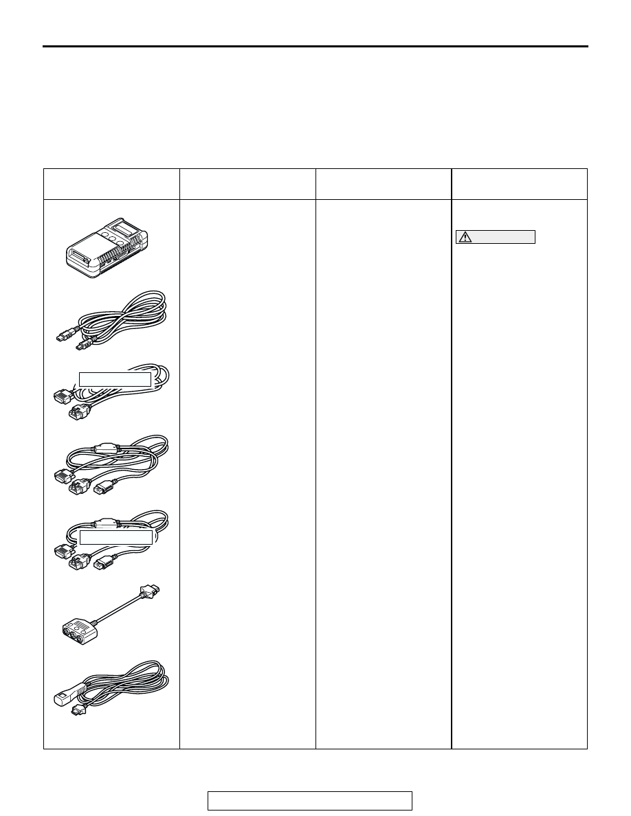
SPECIAL TOOL

M1171000600056

TOOL

TOOL NUMBER AND 
NAME

SUPERSESSION

APPLICATION

MB991958

A: MB991824
B: MB991827
C: MB991910
D: MB991911
E: MB991914
F: MB991825
G: MB991826

MUT-III sub assembly

A: Vehicle 

communication 
interface (V.C.I.)

B: MUT-III USB cable
C: MUT-III main harness 

A (Vehicles with CAN 
communication 
system)

D: MUT-III main harness 

B (Vehicles without 
CAN communication 
system)

E: MUT-III main harness 

C (for Daimler Chrysler 
models only)

F: MUT-III measurement 

adapter

G: MUT-III trigger 

harness

MB991824-KIT
NOTE: G: MB991826 
MUT-III trigger harness is 
not necessary when 
pushing V.C.I. ENTER 
key.

Checking diagnostic 
trouble codes

CAUTION

MUT-III Main Harness B 
(MB991911) should be 
used. MUT-III main 
harness A and C should 
not be used for this 
vehicle.

MB991910

MB991826

MB991958

MB991911

MB991914

MB991824

MB991827

MB991825

DO NOT USE

A

B

C

D

E

F

G

DO NOT USE

ENGINE CONTROL

TSB Revision

ENGINE AND EMISSION CONTROL

17-4

ENGINE CONTROL SYSTEM DIAGNOSIS

INTRODUCTION TO ENGINE CONTROL SYSTEM DIAGNOSIS

M1171002000265

If there is a malfunction in the engine control system, 
the accelerator pedal or throttle body may be faulty.

ENGINE CONTROL SYSTEM DIAGNOSTIC TROUBLESHOOTING STRATEGY

M1171002100295

Use these steps to plan your diagnostic strategy.
If you follow them carefully, you will be sure that you 
have exhausted most of the possible ways to find an 
engine control system fault.
1. Gather information from the customer.

2. Verify that the condition described by the 

customer exists.

3. Find the malfunction by following the Symptom 

Chart.

4. Verify that the malfunction is eliminated.

SYMPTOM CHART

M1171002200311

MB991223

A: MB991219
B: MB991220
C: MB991221
D: MB991222

Harness set

A: Inspection harness
B: LED harness
C: LED harness adapter
D: Probe

General service tools

Checking the continuity 
and measuring the 
voltage at the harness 
connector

MB991348
Test harness set

MB991348-01

Checking throttle position 
sensor

TOOL

TOOL NUMBER AND 
NAME

SUPERSESSION

APPLICATION

MB991223

A

D

C

B

AD

MB991348

SYMPTOM

INSPECTION PROCEDURE

REFERENCE PAGE

Throttle valve will not fully open or close

1

P.17-5

Accelerator pedal operation not smooth 
(over acceleration)

2

P.17-6

ENGINE CONTROL

TSB Revision

ENGINE AND EMISSION CONTROL

17-5

SYMPTOM PROCEDURES

INSPECTION PROCEDURE 1: Throttle Valve Will Not Fully Open or Close

DIAGNOSIS

Required Special Tool:

• MB991958: Scan Tool (MUT-III sub assembly)

• MB991824: V.C.I.

• MB991827: MUT-III USB Cable

• MB991911: MUT-III Main Harness B

STEP 1. Check the accelerator pedal arm return spring.
Q: Is the accelerator pedal arm return spring damaged or 

deformed?
YES : 
Go to Step 2.
NO :  Replace, then go to Step 4.

STEP 2. Clean the throttle body (Refer to GROUP 13A, 

On-vehicle Service 

 Throttle Body Cleaning 

P.13A-993

).

Q: Does the throttle valve fully open and close?

YES : The procedure is complete.
NO :  Go to Step 3.

ENGINE CONTROL

TSB Revision

ENGINE AND EMISSION CONTROL

17-6

STEP 3. Using scan tool MB991958, read the diagnostic 
trouble code.

CAUTION

To prevent damage to scan tool MB991958, always turn the 
ignition switch to the "LOCK" (OFF) position before con-
necting or disconnecting scan tool MB991958.
(1) Ensure that the ignition switch is at the "LOCK" (OFF) 

position.

(2) Start up the personal computer.
(3) Connect special tool MB991827 to special tool MB991824 

and the personal computer.

(4) Connect special tool MB991910 to special tool MB991824.
(5) Connect special tool MB991910 to the data link connector.
(6) Turn the power switch of special tool MB991824 to the "ON" 

position.
NOTE: When special tool MB991824 is energized, special 
tool MB991824 indicator light will be illuminated in a green 
color.

(7) Start the MUT-III system on the personal computer.
(8) Turn the ignition switch to the "ON" position.
(9) Check for MFI system diagnostic trouble code (Refer to 

GROUP 13A, MFI Diagnosis - How to Read and Erase 
Diagnostic Trouble Code 

P.13A-4

).

(10)Turn the ignition switch to the "LOCK" (OFF) position, and 

then remove scan tool MB991958 in the reverse order of 
installation.

Q: Is any DTC set?

YES : Refer to GROUP 13A, Diagnosis 

− Diagnostic 

Trouble Code Chart 

P.13A-26

.

NO :  Go to Step 4.

STEP 4. Retest the system.
Q: Does the throttle valve fully open and close?

YES : The procedure is complete.
NO :  Return to Step 1.

INSPECTION PROCEDURE 2: Accelerator Pedal Operation Not Smooth (Over Acceleration)

DIAGNOSIS

Required Special Tool:

• MB991958: Scan Tool (MUT-III sub assembly)

• MB991824: V.C.I.

• MB991827: MUT-III USB Cable

• MB991911: MUT-III Main Harness B

STEP 1. Check the accelerator pedal.
Q: Is the accelerator pedal loose? 

YES : Tighten, then go to Step 4.
NO :  Go to Step 2.

AC306409AF

MB991911

MB991824

MB991827


Content   ..  397  398  399  400   ..