Mitsubishi Montero (2004+). Manual - part 363


  Index      Mitsubishi     Mitsubishi Montero - service repair manual 2004 year


Search            


Content   ..  361  362  363  364   ..


Mitsubishi Montero (2004+). Manual - part 363


MULTIPORT FUEL INJECTION (MFI) DIAGNOSIS

TSB Revision

MULTIPORT FUEL INJECTION (MFI)

13A-939

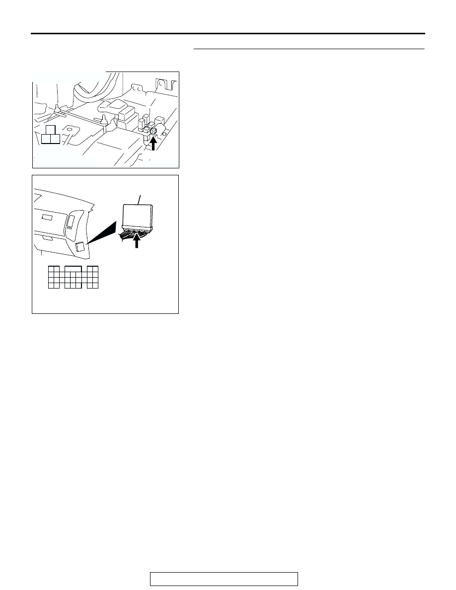
STEP 9. Check connector B-25X at engine speed detection 
and connector D-134 at PCM for damage.
Q: Is the connector in good condition?

YES : Go to Step 10.
NO :  Repair or replace it. Refer to GROUP 00E, Harness 

Connector Inspection 

P.00E-2

. Then confirm that the 

malfunction symptom is eliminated.

AK200979

1

2

3

AB

B-25X

HARNESS 
CONNECTOR: 
COMPONENT SIDE

CONNECTOR: B-25X

AK201166

61

62

63

64

65

66

67

68

69

70

71

76

77

78

79

85

86

87

80

72

73

74

75

81

82

83

84

88

89

CONNECTOR: D-134

AB

PCM

D-134(GR)

HARNESS CONNECTOR: 
COMPONENT SIDE

MULTIPORT FUEL INJECTION (MFI) DIAGNOSIS

TSB Revision

MULTIPORT FUEL INJECTION (MFI)

13A-940

STEP 10. Check for open circuit and short circuit to 
ground and harness damage between engine speed 
detection connector B-25X and PCM connector D-134 
(terminal No. 87).
Q: Is the harness wire in good condition?

YES : Replace the PCM. Then confirm that the malfunction 

symptom is eliminated.

NO :  Repair it. Then confirm that the malfunction symptom 

is eliminated.

AK200979

1

2

3

AB

B-25X

HARNESS 
CONNECTOR: 
COMPONENT SIDE

CONNECTOR: B-25X

AK201166

61

62

63

64

65

66

67

68

69

70

71

76

77

78

79

85

86

87

80

72

73

74

75

81

82

83

84

88

89

CONNECTOR: D-134

AB

PCM

D-134(GR)

HARNESS CONNECTOR: 
COMPONENT SIDE

MULTIPORT FUEL INJECTION (MFI) DIAGNOSIS

TSB Revision

MULTIPORT FUEL INJECTION (MFI)

13A-941

INSPECTION PROCEDURE 32: A/C system.

.

COMMENT

• When the A/C is "ON", the battery positive volt-

age is applied on the PCM (terminal No. 69) from 
the A/C belt lock-ECU. 
When battery positive voltage is applied to the 
PCM, the PCM turns "ON" the power transistor in 
the PCM. The PCM delays A/C engagement 
momentarily while it increases idle rpm. Then the 
A/C compressor clutch relay coil will be ener-
gized. 

With this, the A/C compressor clutch relay turns 
"ON", and the A/C compressor clutch operates.

.

TROUBLESHOOTING HINTS (The most likely 
causes for this case: )

• Malfunction of the A/C control system.

• Malfunction of the A/C switch.

• Improper connector contact, open circuit or 

short-circuited harness wire.

• Malfunction of the PCM.

GREEN-RED

ORANGE

AK302914

8

POWERTRAIN CONTROL MODULE (PCM)

AUTOMATIC
COMPRESSOR
CONTROLLER *

2

A/C COMPRESSOR
RELAY

69

A/C-ECU *

1

*

: AUTOMATIC A/C SYSTEM

*

: MANUAL A/C SYSTEM

A/C Circuit

1

2

3

5

6 7 8 9

4

20

21 22

232425

2627

10111213

14 15

16 1718

19

D-132

(MU803802)

61
656667686970 717273
74757677787980 8182
8384

858687

8889

62

6364

D-134

(MU803804)

AK201038AJ

CONNECTORS: D-132, D-134

PCM

D-134(GR)

D-132(GR)

MULTIPORT FUEL INJECTION (MFI) DIAGNOSIS

TSB Revision

MULTIPORT FUEL INJECTION (MFI)

13A-942

DIAGNOSIS

STEP 1. Check harness connector D-132, D-134 at PCM for 
damage.
Q: Is the harness connector in good condition?

YES : Go to Step 2.
NO :  Repair or replace it. Refer to GROUP 00E, Harness 

Connector Inspection 

P.00E-2

. Then confirm that the 

malfunction symptom is eliminated.

STEP 2. Check the circuit at PCM connector D-132.
(1) Disconnect the connectors D-132 and measure at the 

harness side.

(2) Turn the ignition switch to the "ON" position.

(3) Measure the voltage between terminal No. 8 and ground.

• Voltage should be battery positive voltage.

(4) Using a jumper wire, connect terminal No. 8 to ground.

• A/C compressor relay should turn "ON".

(5) Turn the ignition switch to the "LOCK" (OFF) position.
Q: Is the voltage and A/C compressor relay condition 

normal?
YES : 
Go to Step 3.
NO :  Refer to GROUP 55, Diagnosis 

− Introduction To 

Heater, Air Conditioning And Ventilation Diagnosis 

P.55A-5

. Then confirm that the malfunction symptom 

is eliminated.

AK201281

61

62

63

64

65

66

67

68

69

70

71

76

77

78

79

85

86

87

80

72

73

74

75

81

82

83

84

88

89

2

3

4

5

6

7

8

9

1

10

14

15

16

17

18

19

20

21

22

23

24

25

26

27

11

12

13

CONNECTORS: D-132, D-134

PCM

D-134(GR)

D-132(GR)

AB

D-132 HARNESS CONNECTOR: 
COMPONENT SIDE

D-134 HARNESS CONNECTOR: 
COMPONENT SIDE

AK200938

2

3

4

5

6

7

8

9

1

10

14

15

16

17

18

19

20

21

22

23

24

25

26

27

11

12

13

AB

CONNECTOR: D-132

HARNESS CONNECTOR: 
COMPONENT SIDE

PCM

D-132(GR)

AK201387

2

3

4

5

6

7

8

9

1

10

14

15

16

17

18

19

20

21

22

23

24

25

26

27

11

12

13

D-132 HARNESS 
CONNECTOR: 
COMPONENT SIDE

AK201387AB

2

3

4

5

6

7

8

9

1

10

14

15

16

17

18

19

20

21

22

23

24

25

26

27

11

12

13


Content   ..  361  362  363  364   ..