Mitsubishi Montero (2004+). Manual - part 339


  Index      Mitsubishi     Mitsubishi Montero - service repair manual 2004 year


Search            


Content   ..  337  338  339  340   ..


Mitsubishi Montero (2004+). Manual - part 339


MULTIPORT FUEL INJECTION (MFI) DIAGNOSIS

TSB Revision

MULTIPORT FUEL INJECTION (MFI)

13A-843

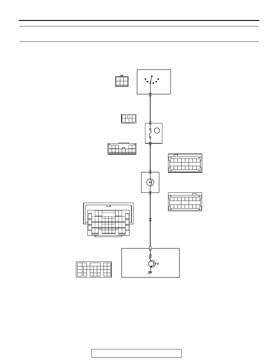
INSPECTION PROCEDURE 4: The Malfunction Indicator Lamp (SERVICE ENGINE SOON or Check 
Engine Lamp) Remains Illuminated and Never Goes Out.

AK201154

RED-

WHITE

RED-

WHITE

BLA

CK-

WHITE

BLUE-

BLA

C

K

14

7

38

37 38

39

40

43

41 42

44

47

45 46

32

31

33 34 35 36

D-04

62

1

2

2

R

IG2

ST

LOCK

ACC

IG1

IGNITION
SWITCH

MALFUNCTION INDICATOR LAMP

SERVICE ENGINE SOON 
OR CHECK ENGINE LAMP

POWERTRAIN
CONTROL
MODULE (PCM)

3

4 5 6

1 2

D-204

5 6

1
3

2

4

D-208

MU801331

9

6

10

17

18

29

2

3 4

7 8

19 20

30 31

12

11

24

33 34 35

21

32

27

26

36 37

28

38

25

13

15

14

16

23

22

1

5

E-111

53 54 55 56 57 58

59

60

63

61 62

64

67

65 66

52

51

D-03

13

3

5

7

12

9

1

6

8

11

10

2

4

D-210

(MU801860)

Malfunction Indicator Lamp (SERVICE ENGINE SOON or Check Engine Lamp) Circuit

(

)

1

2

3

5

6 7 8 9

4

20

21 22

232425

2627

10111213

14 15

16 1718

19

D-132

(MU803802)

6

10A

MULTIPORT FUEL INJECTION (MFI) DIAGNOSIS

TSB Revision

MULTIPORT FUEL INJECTION (MFI)

13A-844

.

CIRCUIT OPERATION

• The malfunction indicator lamp (service engine 

soon or check engine lamp) power is supplied 
from the ignition switch.

• The PCM controls the ground of the malfunction 

indicator lamp (service engine soon or check 
engine lamp) by turning the power transistor in 
the PCM ON and OFF.

.

COMMENT

• In cases such as the above, the cause is proba-

bly that the PCM is detecting a problem in a sen-
sor or actuator, or that one of the malfunctions 
listed at right has probably occurred.

.

AK304351

D-03(GR)

CONNECTOR: D-03

AB

AK201038

CONNECTOR: D-132

AB

PCM

D-132(GR)

AK201041AD

CONNECTOR: D-208

D-208

AK201041AC

CONNECTOR: D-210

D-210

AK304351

D-04(GR)

CONNECTOR: D-04

AC

AK201045

D-204

AB

CONNECTOR: D-204

AK201043

E-111

AB

CONNECTOR: E-111

MULTIPORT FUEL INJECTION (MFI) DIAGNOSIS

TSB Revision

MULTIPORT FUEL INJECTION (MFI)

13A-845

TROUBLESHOOTING HINTS (The most likely 
causes for this case:) 

• Short-circuit between the malfunction indicator 

lamp (service engine soon or check engine lamp) 
and PCM.

• Malfunction of the PCM. 

DIAGNOSIS

Required Special Tools:

• MB991958: Scan Tool (MUT-III Sub Assembly)

• MB991824: V.C.I.

• MB991827: USB Cable

• MB991911: Main Harness B

STEP 1. Using scan tool MB991958, read the diagnostic 
trouble code (DTC).

CAUTION

To prevent damage to scan tool MB991958, always turn the 
ignition switch to the "LOCK" (OFF) position before con-
necting or disconnecting scan tool MB991958.
(1) Connect scan tool MB991958 to the data link connector.
(2) Turn the ignition switch to the "ON" position.
(3) Read the DTC.
(4)  Turn the ignition switch to the "LOCK" (OFF) position.
Q: Is the DTC set?

YES : Refer to Diagnostic Trouble Code Chart 

P.13A-26

NO :  Go to Step 2.

AK302970

AB

MB991911

MB991824

MB991827

MULTIPORT FUEL INJECTION (MFI) DIAGNOSIS

TSB Revision

MULTIPORT FUEL INJECTION (MFI)

13A-846

STEP 2. Check the continuity at combination meter 
harness side connector D-04.
(1) Disconnect the connector D-04 and measure at the harness 

side.

(2) Disconnect the PCM connector D-132.
(3) Check for the continuity between terminal No. 38 and 

ground.

• Should be open loop.

Q: Does continuity exist?

YES : Replace the PCM. Then confirm that the malfunction 

symptom is eliminated.

NO :  Check harness connector E-111 at the intermediate 

connector for damage, and repair or replace as 
required. Refer to GROUP 00E, Harness Connector 
Inspection 

P.00E-2

If intermediate connectors E-111 

is in good condition, repair a short circuit to ground 
between combination meter connector D-04 (terminal 
No. 38) and PCM connector D-132 (terminal No. 7). 
Then confirm that the malfunction symptom is 
eliminated.

AK304355

37

38

39

40

43

41

42

44

47

45

46

32 31

33

34

35

36

D-04(GR)

CONNECTOR: D-04

AB

HARNESS 
CONNECTOR: 
COMPONENT SIDE

AK200938

2

3

4

5

6

7

8

9

1

10

14

15

16

17

18

19

20

21

22

23

24

25

26

27

11

12

13

AB

CONNECTOR: D-132

HARNESS CONNECTOR: 
COMPONENT SIDE

PCM

D-132(GR)

AK201373

37

38

39

40

43

41

42

44

47

45

46

32 31

33

34

35

36

D-04 HARNESS 
CONNECTOR: 
COMPONENT SIDE

AK201373AB

37

38

39

40

43

41

42

44

47

45

46

32 31

33

34

35

36


Content   ..  337  338  339  340   ..