Mitsubishi Montero (2004+). Manual - part 314


  Index      Mitsubishi     Mitsubishi Montero - service repair manual 2004 year


Search            


Content   ..  312  313  314  315   ..


Mitsubishi Montero (2004+). Manual - part 314


MULTIPORT FUEL INJECTION (MFI) DIAGNOSIS

TSB Revision

MULTIPORT FUEL INJECTION (MFI)

13A-743

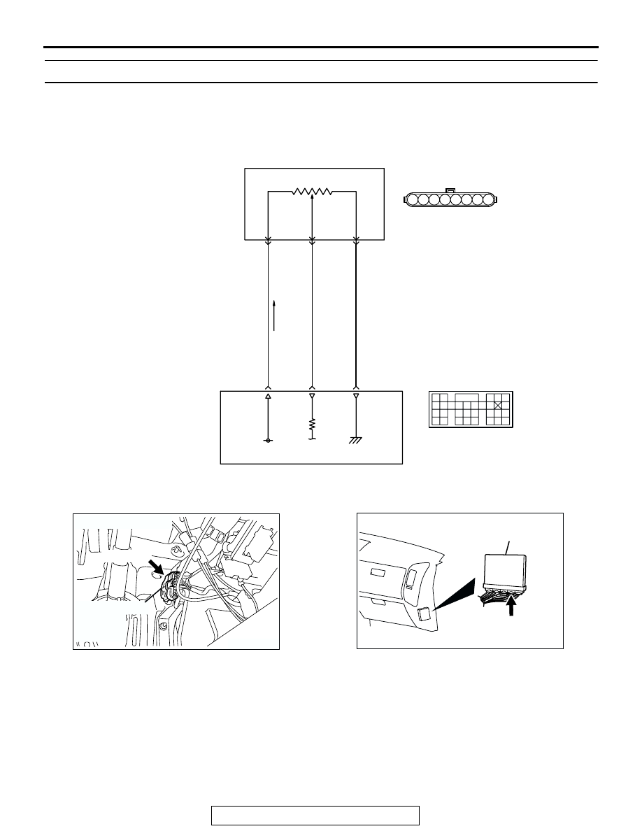
DTC P2122: Accelerator Pedal Position Sensor (Main) Circuit Low Input

.

CIRCUIT OPERATION

• A 5-volt power supply is applied on the APS 

(main) power terminal (terminal No. 2) from the 
PCM (terminal No. 92). 
The ground terminal (terminal No. 1) is grounded 
with PCM (terminal No. 91).

• When the accelerator pedal is moved from the 

idle position to the fully opened position, the 
resistance between the APS (main) output termi-
nal (terminal No. 3) and ground terminal (terminal 
No. 1) will increase according to the rotation.

.

TECHNICAL DESCRIPTION

• The APS (main) outputs voltage which corre-

sponds to the accelerator pedal depression.

AK201163

VIOLET

-WHTE

YELLO

W

-RED

BLA

CK

D-138 

(MU802073)

5 V

92

2

ACCELERATOR 
PEDAL 

POSITION
SENSOR
(MAIN)

POWERTRAIN CONTROL MODULE (PCM)

114

91

3

1

Accelerator Pedal Position Sensor (Main) Circuit

9192

939495

96979899

100

105

113114

115116117

118119120

106

107108109

110111112

101102103

104

D-135

(MU803805)

6 7 8

1 2 3 4 5

AK200944

ACCELERATOR
PEDAL 
POSITION 
SENSOR

AB

D-138(GR)

CONNECTOR: D-138

AK201038AF

CONNECTOR: D-135

PCM

D-135(GR)

MULTIPORT FUEL INJECTION (MFI) DIAGNOSIS

TSB Revision

MULTIPORT FUEL INJECTION (MFI)

13A-744

• The PCM checks whether the voltage is within a 

specified range.

.

DESCRIPTIONS OF MONITOR METHODS
Accelerator pedal position sensor (main) output volt-

age is out of specified range.

.

MONITOR EXECUTION
Continuous

.

MONITOR EXECUTION CONDITIONS (Other 
monitor and Sensor)

Other Monitor (There is no temporary DTC stored 

in memory for the item monitored below)

• Not applicable

Sensor (The sensor below is determined to be 

normal)

• Not applicable

.

DTC SET CONDITIONS

Logic Flow Chart

.

Check Conditions

• Ignition switch "ON" position.

Judgement Criteria

• Accelerator pedal position sensor (main) output 

voltage is 0.2 volt or less for 1 second.

.

OBD-II DRIVE CYCLE PATTERN
None.

.

TROUBLESHOOTING HINTS (The most likely 
causes for this code to be set are:)

• APS failed.

• Open or shorted APS (main) circuit, harness 

damage, or connector damage.

• PCM failed.

START

END

NO

NO

YES

YES

MALFUNCTION

GOOD

CONTINUOUS

FAILURE FOR 1.3sec

OUTPUT VOLTAGE < 0.2V

AK302961

MULTIPORT FUEL INJECTION (MFI) DIAGNOSIS

TSB Revision

MULTIPORT FUEL INJECTION (MFI)

13A-745

DIAGNOSIS

Required Special Tools:

• MB991958: Scan Tool (MUT-III Sub Assembly)

• MB991824: V.C.I.

• MB991827: USB Cable

• MB991911: Main Harness B

STEP 1. Using scan tool MB991958, check data list item 78: 
Accelerator Pedal Position Sensor (main).

CAUTION

To prevent damage to scan tool MB991958, always turn the 
ignition switch to the "LOCK"(OFF) position before con-
necting or disconnecting scan tool MB991958.
(1) Connect scan tool MB991958 to the data link connector.
(2) Turn the ignition switch to the "ON" position.
(3) Set scan tool MB991958 to the data reading mode for item 

78, Accelerator Pedal Position Sensor (main).

• Output voltage is between 0.905 and 1.165 volts when 

foot is released from accelerator pedal.

• Output voltage is 4.035 volts or higher when accelerator 

pedal is fully depressed.

(4) Turn the ignition switch to the "LOCK"(OFF) position.
Q: Is the sensor operating properly?

YES : It can be assumed that this malfunction is intermittent. 

Refer to GROUP 00, How to Use 
Troubleshooting/Inspection. Service Points 

P.00-6

.

NO :  Go to Step 2.

STEP 2. Check connector D-138 at accelerator pedal 
position sensor for damage.
Q: Is the connector in good condition?

YES : Go to Step 3.
NO :  Repair or replace it. Refer to GROUP 00E, Harness 

Connector Inspection 

P.00E-2

. Then go to Step 12.

AK302970

AB

MB991911

MB991824

MB991827

AK200945

3

4

5

1

2

8

6

7

AB

CONNECTOR: D-138

HARNESS 
CONNECTOR: 
COMPONENT SIDE

D-138(GR)

MULTIPORT FUEL INJECTION (MFI) DIAGNOSIS

TSB Revision

MULTIPORT FUEL INJECTION (MFI)

13A-746

STEP 3. Check the accelerator pedal position sensor.
(1) Disconnect the accelerator pedal position sensor connector 

D-138.

(2) Measure resistance between terminal No. 1 and No. 2 and 

between terminal No. 7 and No. 8.

Standard value: 3.5 

 6.5 k

(3) Measure resistance between terminal No. 2 and No. 3 and 

between terminal No. 6 and No. 8.

(4) Move the accelerator pedal from the idle position to the 

full-open position.

• Resistance value changes in accordance with the accel-

erator pedal depression smoothly.

Q: Is the resistance normal?

YES : Go to Step 4.
NO :  Replace the accelerator pedal position sensor. Then 

go to Step 12.

AK200945

3

4

5

1

2

8

6

7

AB

CONNECTOR: D-138

HARNESS 
CONNECTOR: 
COMPONENT SIDE

D-138(GR)

6 7 8

1 2 3 4 5

AK201450

ACCELERATOR PEDAL
POSITION SENSOR
SIDE CONNECTOR

AB

6 7 8

1 2 3 4 5

AK201451

ACCELERATOR PEDAL
POSITION SENSOR
SIDE CONNECTOR

AB


Content   ..  312  313  314  315   ..