Mitsubishi Montero (2004+). Manual - part 312
MULTIPORT FUEL INJECTION (MFI) DIAGNOSIS
TSB Revision
MULTIPORT FUEL INJECTION (MFI)
13A-735
DIAGNOSIS
Required Special Tools:
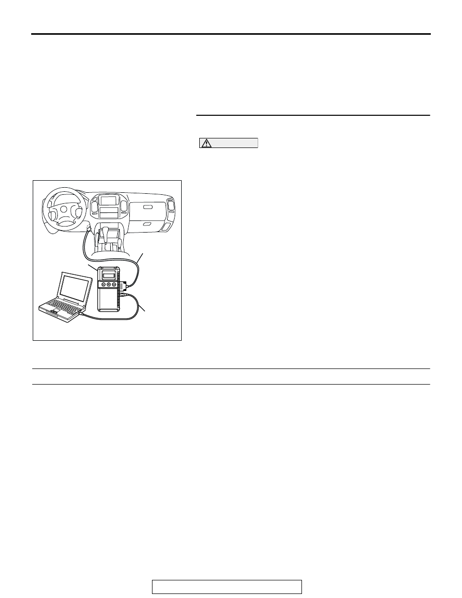
• MB991958: Scan Tool (MUT-III Sub Assembly)
• MB991824: V.C.I.
• MB991827: USB Cable
• MB991911: Main Harness B
STEP 1. Using scan tool MB991958, read the diagnostic
trouble code (DTC).
CAUTION
To prevent damage to scan tool MB991958, always turn the
ignition switch to the "LOCK"(OFF) position before con-
necting or disconnecting scan tool MB991958.
(1) Connect scan tool MB991958 to the data link connector.
(2) Turn the ignition switch to the "ON" position.
(3) After the DTC has been deleted, read the DTC again.
(4) Turn the ignition switch to the "LOCK"(OFF) position.
Q: Is DTC P2108 set?
YES : Replace the PCM.
NO : It can be assumed that this malfunction is intermittent.
Refer to GROUP 00, How to Use
Troubleshooting/Inspection. Service Points
.
DTC P2121: Accelerator Pedal Position Sensor (Main) Circuit Range/Performance Problem
.
Accelerator Pedal Position Sensor (main) Circuit
Range/Performance Problem Circuit
• Refer to DTC P2122 − Accelerator Pedal Position
Sensor (main) Circuit
• Refer to INSPECTION PROCEDURE 33 − Accel-
erator Pedal Position Switch Circuit
.
.
CIRCUIT OPERATION
• Refer to, DTC P2122 − Accelerator Pedal Posi-
tion Sensor (main) Circuit
.
• Refer to INSPECTION PROCEDURE 33 − Accel-
erator Pedal Position Switch Circuit
.
.
TECHNICAL DESCRIPTION
• PCM checks the APS (main) output signal char-
acteristics for abnormal conditions.
.
DESCRIPTIONS OF MONITOR METHODS
• Accelerator pedal position sensor (main) output
voltage is greater than that the specified value
when the accelerator pedal position switch is on.
.
MONITOR EXECUTION
• Continuous
.
MONITOR EXECUTION CONDITIONS (Other
monitor and Sensor)
Other Monitor (There is no temporary DTC stored
in memory for the item monitored below)
• Not applicable
Sensor (The sensor below is determined to be
normal)
• Not applicable
.
AK302970
AB
MB991911
MB991824
MB991827