Mitsubishi Montero (2004+). Manual - part 305
MULTIPORT FUEL INJECTION (MFI) DIAGNOSIS
TSB Revision
MULTIPORT FUEL INJECTION (MFI)
13A-707
DTC P1601: Communication Malfunction (between PCM and Throttle Actuator Control Module)
.
TECHNICAL DESCRIPTION
• PCM checks the communication lines for abnor-
mal conditions.
.
DESCRIPTIONS OF MONITOR METHODS
Communication with throttle actuator control module
is impossible.
.
MONITOR EXECUTION
Continuous
.
MONITOR EXECUTION CONDITIONS (Other
monitor and Sensor)
Other Monitor (There is no temporary DTC stored
in memory for the item monitored below)
• Not applicable
Sensor (The sensor below is determined to be
normal)
• Not applicable
.
DTC SET CONDITIONS
Check Conditions
• Battery positive voltage is higher than 6.3 volts.
Judgement Criteria
• PCM detects an error in communication with the
throttle actuator control module for 0.05 second.
• Throttle actuator control module detects an error
in communication with the PCM for 0.125 sec-
ond.
.
TROUBLESHOOTING HINTS (The most likely
causes for this code to be set are:)
• PCM failed.
DIAGNOSIS
Required Special Tools:
• MB991958: Scan Tool (MUT-III Sub Assembly)
• MB991824: V.C.I.
• MB991827: USB Cable
• MB991911: Main Harness B
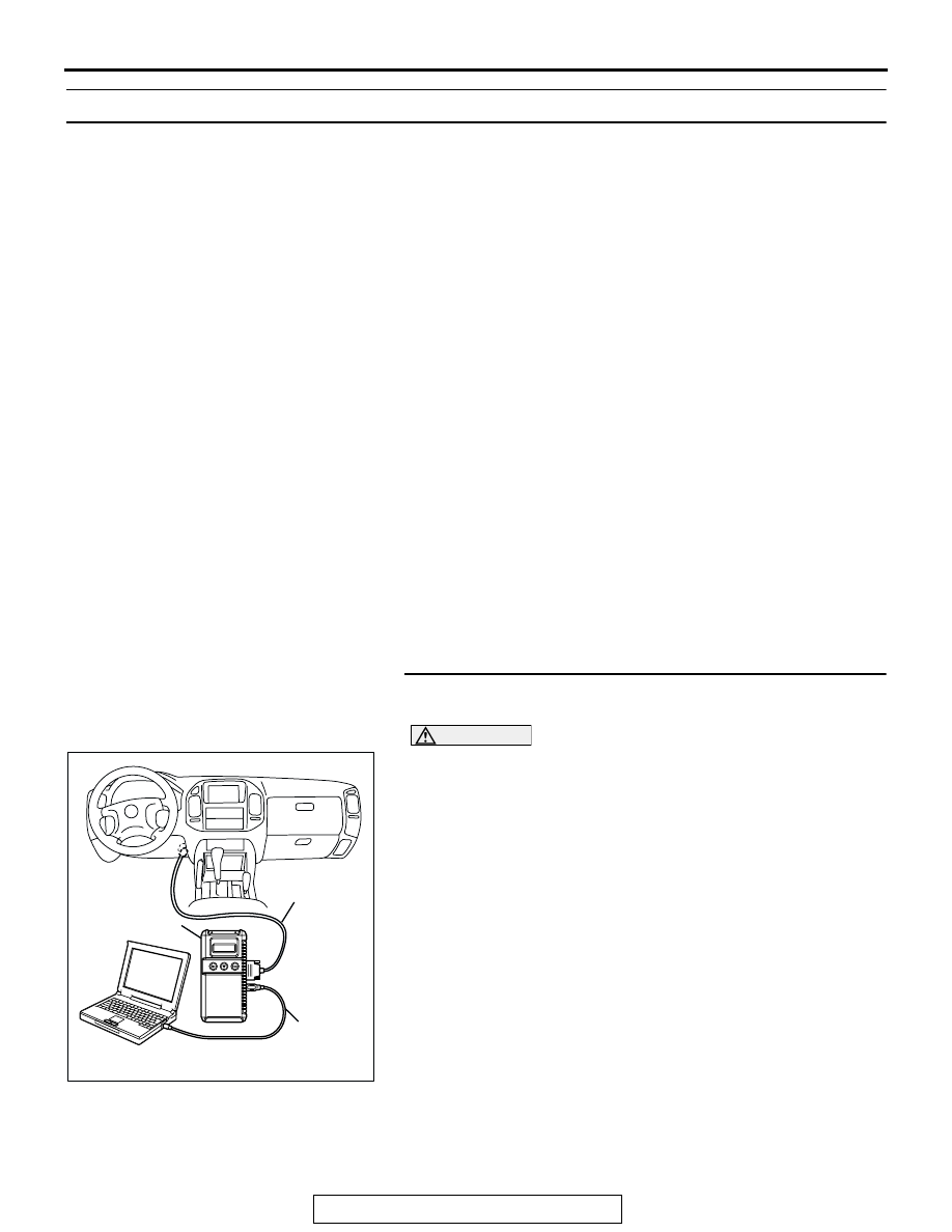
STEP 1. Using scan tool MB991958, read the diagnostic
trouble code (DTC)
CAUTION
To prevent damage to scan tool MB991958, always turn the
ignition switch to the "LOCK"(OFF) position before con-
necting or disconnecting scan tool MB991958.
(1) Connect scan tool MB991958 to the data link connector.
(2) Turn the ignition switch to the "ON" position.
(3) After the DTC has been deleted, read the DTC again.
(4) Turn the ignition switch to the "LOCK"(OFF) position.
Q: Is DTC P01601 set?
YES : Replace the PCM.
NO : It can be assumed that this malfunction is intermittent.
Refer to GROUP 00, How to Use
Troubleshooting/Inspection Service Points
AK302970
AB
MB991911
MB991824
MB991827