Mitsubishi Montero (2004+). Manual - part 272
MULTIPORT FUEL INJECTION (MFI) DIAGNOSIS
TSB Revision
MULTIPORT FUEL INJECTION (MFI)
13A-575
STEP 15. Perform the OBD-II drive cycle.
(1) Carry out a test drive with the drive cycle pattern (Refer to
Diagnostic Function
− OBD-ll Drive Cycle − Procedure 1 −
Evaporative Emission System Leak Monitor
(2) Read the diagnostic trouble code (DTC).
Q: Is DTC P0451 set?
YES : Repeat the troubleshooting from Step 2.
NO : The procedure is complete.
DTC P0452: Evaporative Emission System Pressure Sensor Low Input
AC203991
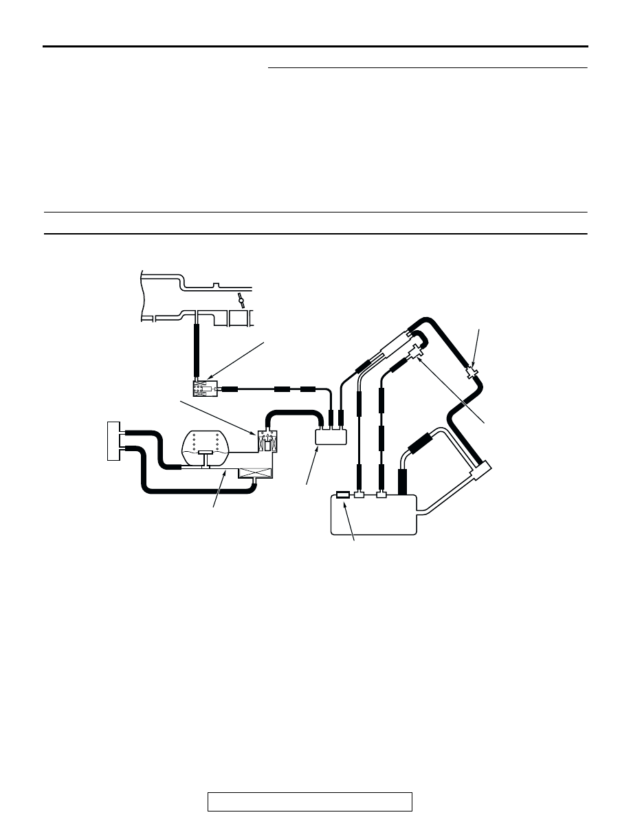
SYSTEM DIAGRAM
A
B
C
D
E
F
G
H
I
J
K
L
M
N
O
Q
S
R
P
FUEL TANK
CHECK VALVE B
CHECK VALVE A
EVAPORATIVE
EMISSION
PURGE
SOLENOID
EVAPORATIVE EMISSION
VENTILATION SOLENOID
EVAPORATIVE
EMISSION
CANISTER
VENT PIPE
ASSEMBLY
AC
FUEL TANK DIFFERENTIAL
PRESSURE SENSOR
ONBOARD REFUELING
VAPOR RECOVERY(ORVR)
VENT VALVE MODULE