Mitsubishi Montero (2004+). Manual - part 271


  Index      Mitsubishi     Mitsubishi Montero - service repair manual 2004 year


Search            


Content   ..  269  270  271  272   ..


Mitsubishi Montero (2004+). Manual - part 271


MULTIPORT FUEL INJECTION (MFI) DIAGNOSIS

TSB Revision

MULTIPORT FUEL INJECTION (MFI)

13A-571

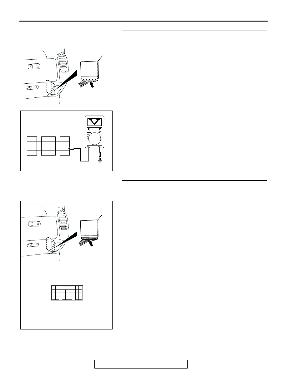
STEP 10. Measure the signal voltage at PCM connector 
D-134 by backprobing.
(1) Do not disconnect PCM connector D-134.
(2) Turn the ignition switch to the "ON" position.
(3) Remove the fuel cap.

(4) Measure the voltage between PCM connector D-134 

terminal 82 and ground by backprobing.

• The voltage should measure between 2.0 and 3.0 volts.

(5) Turn the ignition switch to the "LOCK" (OFF) position.
Q: Is the measured voltage between 2.0 and 3.0 volts?

YES : Go to Step 14.
NO :  Go to Step 11.

STEP 11. Check PCM connector D-134 for loose, corroded 
or damaged terminals, or terminals pushed back in the 
connector.
Q: Are the connector and terminals in good condition?

YES : Go to Step 12.
NO :  Repair or replace the faulty component. (Refer to 

GROUP 00E, Harness Connector Inspection 

P.00E-2

). Go to Step 15.

AC203993

CONNECTOR: D-134

AD

D-134 (GR)

PCM

AC204161

64

63

65 66 67 68

62

61

69 70 71 72 73

74 75 76 77 78 79 8081 82
83 84

85 86 87

88 89

AB

D-134 HARNESS CONNECTOR:
HARNESS SIDE

AC203997

CONNECTOR: D-134

AC

D-134 (GR)

PCM

D-134 HARNESS CONNECTOR:
HARNESS SIDE

64

63

65 66 67 68

62

61

69 70 71 72 73

74 75 76 77 78 79 80 81 82
83 84

85 86 87

88 89

MULTIPORT FUEL INJECTION (MFI) DIAGNOSIS

TSB Revision

MULTIPORT FUEL INJECTION (MFI)

13A-572

STEP 12. Check intermediate connectors D-112, E-111 and 
F-07, and fuel tank differential pressure sensor connector 
G-05 for loose, corroded or damaged terminals, or 
terminals pushed back in the connector.
Q: Are the connectors and terminals in good condition?

YES : Go to Step 13.
NO :  Repair or replace the faulty component. (Refer to 

GROUP 00E, Harness Connector Inspection 

P.00E-2

). Go to Step 15.

AC203998

CONNECTOR: D-112

AC

D-112

D-112 HARNESS
CONNECTOR:
COMPONENT SIDE

38

28

16

33

22

10

31

19

7

1

18

30

29

17

5

6

21

20

32

8

2

9

25

13

3

24

23

34 35

11 12

27

26

36 37

14

4

15

AC203999

CONNECTOR: E-111

AC

E-111

E-111 HARNESS
CONNECTOR:
COMPONENT SIDE

38

12 13

11

26

14

1

20

6

23 24 25

37

31

36

30

10

9

21 22

35

8

7

34

17

29

18 19

5

4

15 16

33

28

32

27

3

2

AC204000

CONNECTOR: F-07

AC

F-07 (B)

F-07 HARNESS
CONNECTOR:
COMPONENT SIDE

8

4

3

2

1
5 6 7

ACX00218

CONNECTOR : G-05

AR

G-05 (B)

SECOND SEAT UNDER
SERVICE HOLE

G-05 HARNESS
CONNECTOR:
COMPONENT SIDE

1

2

3

MULTIPORT FUEL INJECTION (MFI) DIAGNOSIS

TSB Revision

MULTIPORT FUEL INJECTION (MFI)

13A-573

STEP 13. Check the harness wires between PCM 
connector D-134 terminal 82 and fuel tank differential 
pressure sensor connector G-05 terminal 1 for damage. 
Q: Are the harness wires in good condition?

YES : It can be assumed that this malfunction is intermittent. 

(Refer to GROUP 00, How to Use 
Troubleshooting/Inspection Service Points 

− How to 

Cope with Intermittent Malfunction 

P.00-6

). Go to 

Step 15.

NO :  Repair the damaged harness wires. Go to Step 15.

AC203997

CONNECTOR: D-134

AC

D-134 (GR)

PCM

D-134 HARNESS CONNECTOR:
HARNESS SIDE

64

63

65 66 67 68

62

61

69 70 71 72 73

74 75 76 77 78 79 80 81 82
83 84

85 86 87

88 89

ACX00218

CONNECTOR : G-05

AR

G-05 (B)

SECOND SEAT UNDER
SERVICE HOLE

G-05 HARNESS
CONNECTOR:
COMPONENT SIDE

1

2

3

MULTIPORT FUEL INJECTION (MFI) DIAGNOSIS

TSB Revision

MULTIPORT FUEL INJECTION (MFI)

13A-574

STEP 14. Using scan tool MB991958, check data list item 
73: Fuel Tank Differential Pressure Sensor.

CAUTION

To prevent damage to scan tool MB991958, always turn the 
ignition switch to the "LOCK" (OFF) position before con-
necting or disconnecting scan tool MB991958.
(1) Connect scan tool MB991958 to the data link connector.

(2) Disconnect hose F from the evaporative emission canister 

side, and plug the hose.

(3) Turn the ignition switch to the "ON" position.
(4) Remove the fuel cap.
(5) Set scan tool MB991958 to the data reading mode.

Item 73, Fuel Tank Differential Pressure Sensor.

• The fuel tank pressures reading on the scan tool 

should be 

−1.5 to 1.5 kPa (−0.443 to 0.443 inHg).

(6) Connect an evaporative emission system pressure pump to 

the fuel tank filler tube and pressurize the fuel tank.

• The fuel tank pressure reading should increase.

(7) Disconnect an evaporative emission system pressure pump 

and connect hose F.

(8) Turn the ignition switch to the "LOCK" (OFF) position and 

disconnect scan tool MB991958.

Q: Is the fuel tank pressure between 

1.5 and 1.5 kPa 

(

0.443 and 0.443 inHg)?

YES : It can be assumed that this malfunction is intermittent. 

(Refer to GROUP 00, How to Use 
Troubleshooting/Inspection Service Points 

− How to 

Cope with Intermittent Malfunction 

P.00-6

). Go to 

Step 15.

NO :  Replace the PCM (Refer to 

P.13A-1014

). Go to Step 

15       .

AC306409AF

MB991911

MB991824

MB991827

AC102602 AC

HOSE F

ACX01358


Content   ..  269  270  271  272   ..