Mitsubishi Montero (2004+). Manual - part 251


  Index      Mitsubishi     Mitsubishi Montero - service repair manual 2004 year


Search            


Content   ..  249  250  251  252   ..


Mitsubishi Montero (2004+). Manual - part 251


MULTIPORT FUEL INJECTION (MFI) DIAGNOSIS

TSB Revision

MULTIPORT FUEL INJECTION (MFI)

13A-491

STEP 3. Check the trouble symptoms.
(1) Carry out a test drive with the drive cycle pattern. Refer to 

Diagnostic Function

− OBD-II Drive Cycle − Procedure 6 − 

Other Monitor 

P.13A-4

.

(2) Check the diagnostic trouble code (DTC).
Q: Is DTC P0340 set?

YES : Replace the PCM. Then go to Step 21.
NO :  It can be assumed that this malfunction is intermittent. 

Refer to GROUP 00, How to Use 
Troubleshooting/Inspection Service Points 

P.00-6

.

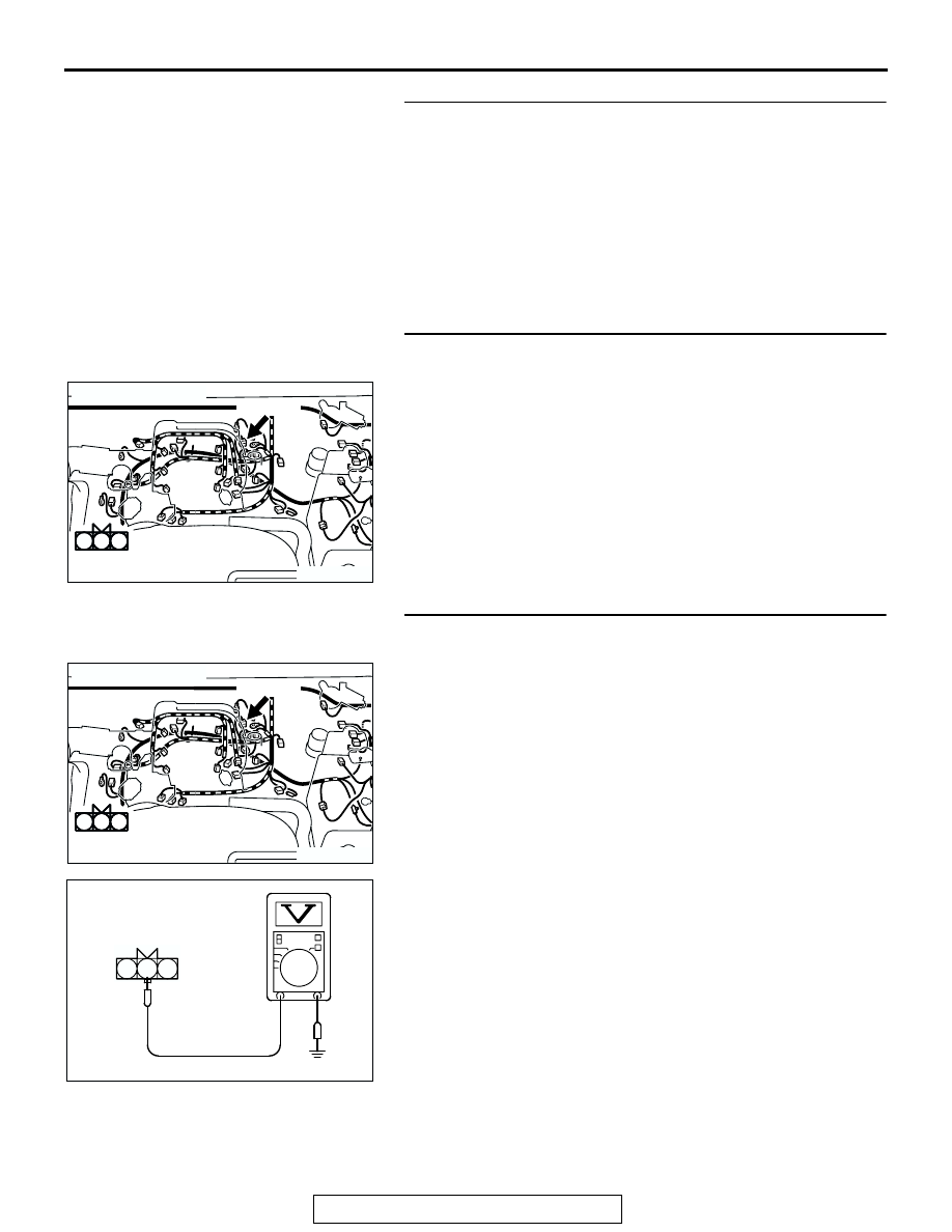
STEP 4. Check connector B-08 at camshaft position 
sensor intermediate connector for damage.
Q: Is the connector in good condition?

YES : Go to Step 5.
NO :  Repair or replace it. Refer to GROUP 00E, Harness 

Connector Inspection 

P.00E-2

. Then go to Step 21.

STEP 5. Measure the sensor supply voltage at camshaft 
position sensor intermediate connector B-08.
(1) Disconnect the camshaft position sensor intermediate 

connector B-08 and measure at the female side.

(2) Turn the ignition switch to the "ON" position.

(3) Measure the voltage between terminal No. 2 and ground.

• Voltage should be between 4.8 and 5.2 volts.

(4) Turn the ignition switch to the "LOCK" (OFF) position.
Q: Is the measured voltage between 4.8 and 5.2 volts?

YES : Go to Step 10.
NO :  Go to Step 6.

AK302432

3 2 1

B-08(GR)

3 2 1

AB

CONNECTOR: B-08

HARNESS CONNECTOR:
COMPONENT SIDE

3 2 1

AK302432

3 2 1

B-08(GR)

3 2 1

AB

CONNECTOR: B-08

HARNESS CONNECTOR:
COMPONENT SIDE

3 2 1

1

2

3

AK302947

B-08 HARNESS 
CONNECTOR: 
COMPONENT SIDE

AB

MULTIPORT FUEL INJECTION (MFI) DIAGNOSIS

TSB Revision

MULTIPORT FUEL INJECTION (MFI)

13A-492

STEP 6. Measure the sensor supply voltage at PCM 
connector D-134 by backprobing.
(1) Do not disconnect the PCM connector D-134.
(2) Disconnect the camshaft position sensor intermediate 

connector B-08.

(3) Turn the ignition switch to the "ON" position.

(4) Measure the voltage between terminal No. 71 and ground 

by backprobing.

• Voltage should be between 4.8 and 5.2 volts.

(5) Turn the ignition switch to the "LOCK" (OFF) position.
Q: Is the measured voltage between 4.8 and 5.2 volts?

YES : Go to Step 7.
NO :  Go to Step 8.

STEP 7. Check connector D-134 at PCM for damage.
Q: Is the connector in good condition?

YES : Repair harness wire between camshaft position 

sensor intermediate connector B-08 (terminal No. 2) 
and PCM connector D-134 (terminal No. 71) because 
of open circuit. Then go to Step 20.

NO :  Repair or replace it. Refer to GROUP 00E, Harness 

Connector Inspection 

P.00E-2

. Then go to Step 21.

AK201166

61

62

63

64

65

66

67

68

69

70

71

76

77

78

79

85

86

87

80

72

73

74

75

81

82

83

84

88

89

CONNECTOR: D-134

AB

PCM

D-134(GR)

HARNESS CONNECTOR: 
COMPONENT SIDE

AK302431

61
656667686970 717273
74757677787980 8182
8384

858687

8889

62

6364

D-134 HARNESS 
CONNECTOR: 
HARNESS SIDE

AB

AK201166

61

62

63

64

65

66

67

68

69

70

71

76

77

78

79

85

86

87

80

72

73

74

75

81

82

83

84

88

89

CONNECTOR: D-134

AB

PCM

D-134(GR)

HARNESS CONNECTOR: 
COMPONENT SIDE

MULTIPORT FUEL INJECTION (MFI) DIAGNOSIS

TSB Revision

MULTIPORT FUEL INJECTION (MFI)

13A-493

STEP 8. Check connector D-134 at PCM for damage.
Q: Is the connector in good condition?

YES : Go to Step 9.
NO :  Repair or replace it. Refer to GROUP 00E, Harness 

Connector Inspection 

P.00E-2

. Then go to Step 21.

STEP 9. Check for short circuit to ground between 
camshaft position sensor intermediate connector B-08 
(terminal No. 2) and PCM connector D-134 (terminal No. 
71).
Q: Is the harness wire in good condition?

YES : Replace the PCM. Then go to Step 21.
NO :  Repair it. Then go to Step 21.

AK201166

61

62

63

64

65

66

67

68

69

70

71

76

77

78

79

85

86

87

80

72

73

74

75

81

82

83

84

88

89

CONNECTOR: D-134

AB

PCM

D-134(GR)

HARNESS CONNECTOR: 
COMPONENT SIDE

AK302432

3 2 1

B-08(GR)

3 2 1

AB

CONNECTOR: B-08

HARNESS CONNECTOR:
COMPONENT SIDE

3 2 1

AK201166

61

62

63

64

65

66

67

68

69

70

71

76

77

78

79

85

86

87

80

72

73

74

75

81

82

83

84

88

89

CONNECTOR: D-134

AB

PCM

D-134(GR)

HARNESS CONNECTOR: 
COMPONENT SIDE

MULTIPORT FUEL INJECTION (MFI) DIAGNOSIS

TSB Revision

MULTIPORT FUEL INJECTION (MFI)

13A-494

STEP 10. Measure the power supply voltage at camshaft 
position sensor intermediate connector B-08.
(1) Disconnect the connector B-08 and measure at the female 

side.

(2) Turn the ignition switch to the "ON" position.

(3) Measure the voltage between terminal No. 3 and ground.

• Voltage should be battery positive voltage.

(4) Turn the ignition switch to the "LOCK" (OFF) position.
Q: Is battery positive voltage (approximately 12 volts) 

present?
YES : 
Go to Step 12.
NO :  Go to Step 11.

STEP 11. Check connector B-22X at the MFI relay for 
damage.
Q: Is the connector in good condition?

YES : Repair harness wire between MFI relay connector 

B-22X (terminal No. 1) and camshaft position sensor 
intermediate connector B-08 (terminal No. 3) because 
of open circuit or short circuit to ground. Then go to 
Step 20.

NO :  Repair or replace it. Refer to GROUP 00E, Harness 

Connector Inspection 

P.00E-2

. Then go to Step 21.

AK302432

3 2 1

B-08(GR)

3 2 1

AB

CONNECTOR: B-08

HARNESS CONNECTOR:
COMPONENT SIDE

3 2 1

1

2

3

AK302948

B-08 HARNESS 
CONNECTOR: 
MALE SIDE

AB

AK200951

2 1

3

4

B-22X

AB

CONNECTOR: B-22X

HARNESS 
CONNECTOR: 
COMPONENT SIDE


Content   ..  249  250  251  252   ..