Mitsubishi Montero (2004+). Manual - part 240


  Index      Mitsubishi     Mitsubishi Montero - service repair manual 2004 year


Search            


Content   ..  238  239  240  241   ..


Mitsubishi Montero (2004+). Manual - part 240


MULTIPORT FUEL INJECTION (MFI) DIAGNOSIS

TSB Revision

MULTIPORT FUEL INJECTION (MFI)

13A-447

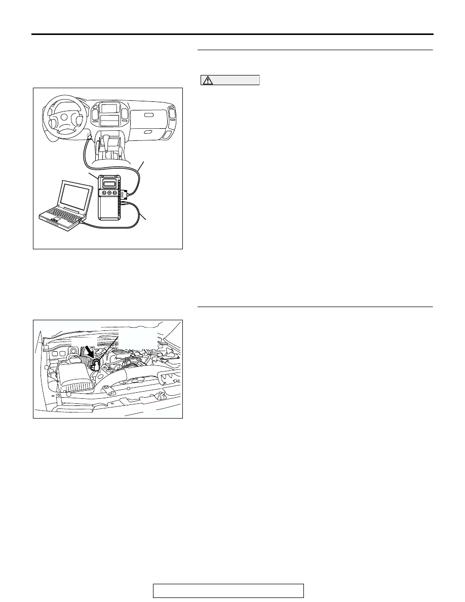
STEP 6. Using scan tool MB991958, check data list item 14: 
Throttle Position Sensor (sub).

CAUTION

To prevent damage to scan tool MB991958, always turn the 
ignition switch to the "LOCK"(OFF) position before con-
necting or disconnecting scan tool MB991958
(1) Connect scan tool MB991958 to the data link connector.
(2) Turn the ignition switch to the "ON" position.
(3) Detach the intake air hose at the throttle body.
(4) Disconnect the connector of the throttle position sensor.
(5) Use test harness special tool (MB991658) to connect only 

terminals No. 1, No. 2, No. 3, and No. 4.

(6) Set scan tool MB991958 to the data reading mode for item 

14, Throttle Position Sensor (sub).

• Output voltage should be between 2.2 and 2.8 volts 

when the throttle valve is fully closed with your finger.

• Output voltage should be 4.0 volts or more when the 

throttle valve is fully open with your finger.

(7) Turn the ignition switch to the "LOCK"(OFF) position.
Q: Is the sensor operating properly?

YES : It can be assumed that this malfunction is intermittent. 

Refer to GROUP 00, How to Use 
Troubleshooting/Inspection Service Points 

P.00-6

.

NO :  Replace the PCM. Then go to Step 8. 

STEP 7. Replace the throttle body assembly.
(1) Replace the throttle body assembly.
(2) Turn the ignition switch to the "ON" position.
(3) After the DTC has been deleted, read the DTC again.
(4) Turn the ignition switch to the "LOCK" (OFF) position.
Q: Is DTC P0223 set?

YES : Replace the PCM. Then go to Step 8.
NO :  The procedure is complete.

AK302970

AB

MB991911

MB991824

MB991827

AK201173

THROTTLE 
POSITION 
SENSOR

AB

B-05(B)

CONNECTOR: B-05

MULTIPORT FUEL INJECTION (MFI) DIAGNOSIS

TSB Revision

MULTIPORT FUEL INJECTION (MFI)

13A-448

STEP 8. Using scan tool MB991958, read the diagnostic 
trouble code (DTC).

CAUTION

To prevent damage to scan tool MB991958, always turn the 
ignition switch to the "LOCK"(OFF) position before con-
necting or disconnecting scan tool MB991958.
(1) Connect scan tool MB991958 to the data link connector.
(2) Turn the ignition switch to the "ON" position.
(3) After the DTC has been deleted, read the DTC again.
(4) Turn the ignition switch to the "LOCK"(OFF) position.
Q: Is DTC P0223 set?

YES : Retry the troubleshooting.
NO :  The inspection is complete.

DTC P0300: Random/Multiple Cylinder Misfire Detected 

.

Random Misfire Circuit

• Refer to DTC P0335 − Crankshaft Position Sen-

sor Circuit. 

P.13A-467

• Refer to DTC P0201 − P0206, Injector Circuit. 

P.13A-421

.

CIRCUIT OPERATION

• Refer to DTC P0335 − Crankshaft Position Sen-

sor Circuit. 

P.13A-467

• Refer to DTC P0201 − P0206, Injector Circuit. 

P.13A-421

.

TECHNICAL DESCRIPTION

• If a misfire occurs while the engine is running, the 

engine speed changes for an instant.

• The PCM checks for such changes in engine 

speed.

.

DESCRIPTIONS OF MONITOR METHODS
Monitor angular acceleration of crankshaft and 

detect malfunction when negative variation of the 
angular acceleration is large.

.

MONITOR EXECUTION
Continuous

.

MONITOR EXECUTION CONDITIONS (Other 
monitor and Sensor)

Other Monitor (There is no temporary DTC stored 

in memory for the item monitored below)

• Not applicable

Sensor (The sensor below is determined to be 

normal)

• Camshaft position sensor

• Volume airflow sensor

• Engine coolant temperature sensor

• Intake air temperature sensor

• Barometric pressure sensor

• Throttle position sensor

.

AK302970

AB

MB991911

MB991824

MB991827

MULTIPORT FUEL INJECTION (MFI) DIAGNOSIS

TSB Revision

MULTIPORT FUEL INJECTION (MFI)

13A-449

DTC SET CONDITIONS

Logic Flow Chart

.

Check Conditions

• Engine speed is between 440 and 6,000 r/min.

• Engine coolant temperature is higher than −10°C 

(14

°F).

• Barometric pressure is higher than 76 kPa (22.4 

in.Hg).

• Volumetric efficiency is between 30 and 60 per-

cent.

• Adaptive learning is complete for the vane which 

generates a crankshaft position signal.

• While the engine is running, excluding gear shift-

ing, deceleration, sudden acceleration/decelera-
tion and A/C compressor switching. 

• The throttle deviation is −0.06 V/10 ms to +0.06 

V/10 ms.

START

MONITORING

CONDITIONS

CALCULATE CRANKSHAFT

ANGULAR ACCELERATION (An)

An < TH

MF

 (Ne,   v)

MISFIRE

CALCULATE PERCENT MISFIRE (R

MF

)

END

NO

NO

NO

NO

NO

NO

YES

YES

YES

YES

YES

YES

GOOD

WITHIN 1000rev

R

MF

 > SPECIFIED VALUE

MALFUNCTION

(EXCEED STD  ×1.5)

GOOD

MALFUNCTION

(DAMAGE THE CAT.)

GOOD

R

MF

 > TH

CD

 (Ne,   v)

CALCULATE PERCENT MISFIRE (R

MF

)

WITHIN 200rev

Ne: ENGINE SPEED
   v: VOLUMETRIC EFFICIENCY

AK302943

MULTIPORT FUEL INJECTION (MFI) DIAGNOSIS

TSB Revision

MULTIPORT FUEL INJECTION (MFI)

13A-450

Judgement Criteria (change in the angular accel-

eration of the crankshaft is used for misfire 
detection).

• Misfire has occurred more frequently than 

allowed during the last 200 revolutions [when the 
catalyst temperature is higher than 950

°C 

(1742

°F)].

or

• Misfire has occurred in 20 or more of the last 

1,000 revolutions (corresponding to 1.5 times the 
limit of emission standard).

.

OBD-II DRIVE CYCLE PATTERN
Refer to Diagnostic Function 

− OBD-II Drive Cycle − 

Procedure 6 

− Other Monitor 

P.13A-4

.

.

TROUBLESHOOTING HINTS (The most likely 
causes for this code to be set are: )

• Ignition system related part(s) failed.

• Poor crankshaft position sensor.

• Incorrect air/fuel ratio.

• Low compression pressure.

• Skipping of timing belt teeth.

• EGR system and EGR valve failed.

• PCM failed.

DIAGNOSIS

Required Special Tools:

• MB991958: Scan tool (MUT-III Sub Assembly)

• MB991824: V.C.I.

• MB991827: USB Cable

• MB991911: Main Harness B

STEP 1. Using scan tool MB991958, check data list item 22: 
Crankshaft Position Sensor.

CAUTION

To prevent damage to scan tool MB991958, always turn the 
ignition switch to the "LOCK" (OFF) position before con-
necting or disconnecting scan tool MB991958.
(1) Connect scan tool MB991958 to the data link connector.
(2) Start the engine and run at idle.
(3) Set scan tool MB991958 to the data reading mode for item 

22, Crankshaft Position Sensor.

(4) Check the waveform of the crankshaft position sensor while 

keeping the engine speed constant.

• The pulse width should be constant.

Q: Is the sensor operating properly?

YES : Go to Step 2.
NO :  Refer to DTC P0335 

− Crankshaft Position Sensor 

Circuit Malfunction. 

P.13A-467

AK302970

AB

MB991911

MB991824

MB991827


Content   ..  238  239  240  241   ..