Mitsubishi Montero (2004+). Manual - part 239
MULTIPORT FUEL INJECTION (MFI) DIAGNOSIS
TSB Revision
MULTIPORT FUEL INJECTION (MFI)
13A-443
TECHNICAL DESCRIPTION
• The throttle position sensor (sub) outputs voltage
which corresponds to the throttle valve opening
angle.
• The PCM checks whether the voltage is within a
specified range.
.
DESCRIPTIONS OF MONITOR METHODS
Throttle position sensor (sub) output voltage is out of
specified range.
.
MONITOR EXECUTION
Continuous
.
MONITOR EXECUTION CONDITIONS (Other
monitor and Sensor)
Other Monitor (There is no temporary DTC stored
in memory for the item monitored below)
• Not applicable
Sensor (The sensor below is determined to be
normal)
• Volume airflow sensor
.
DTC SET CONDITIONS
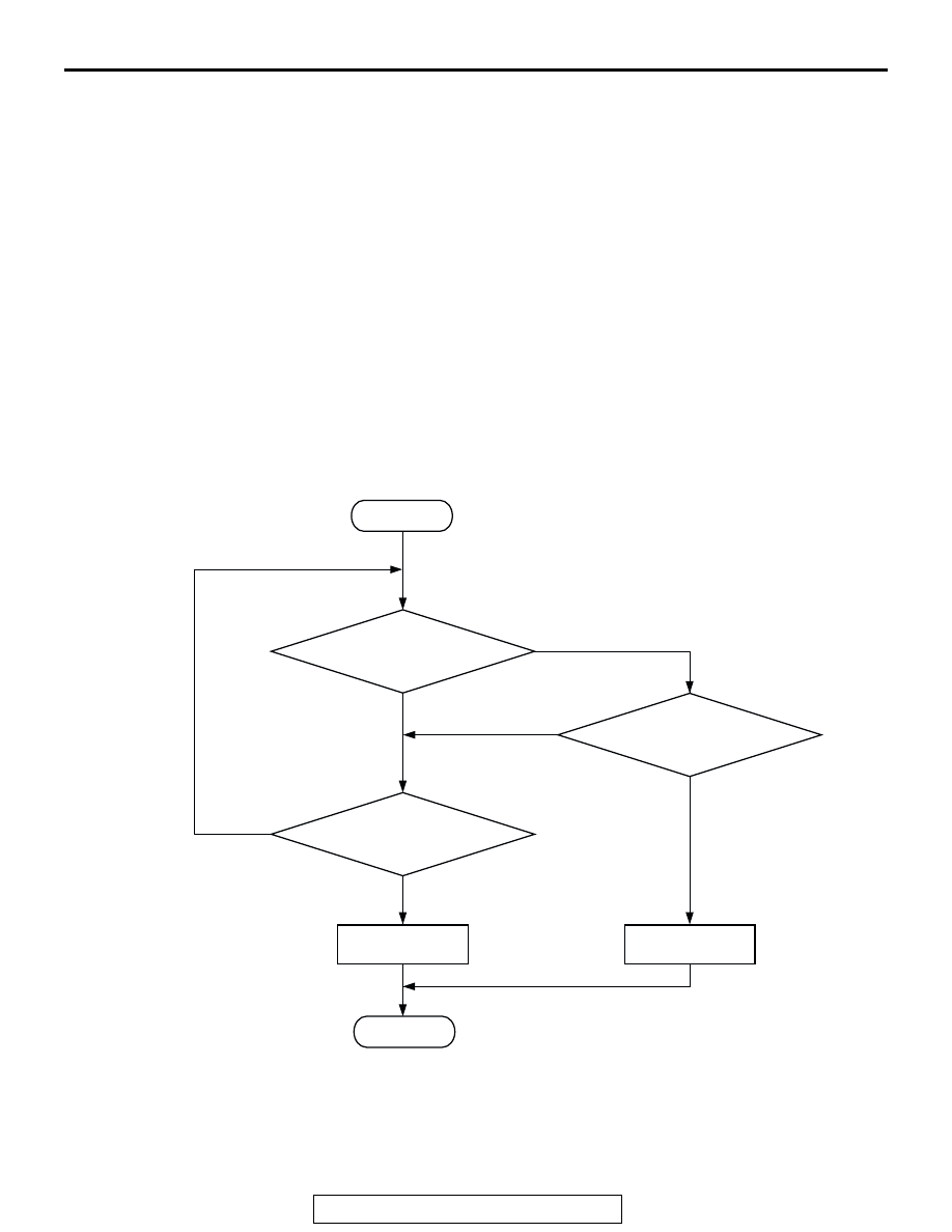
Logic Flow Chart
.
Check Conditions
• Ignition switch "ON" position.
Judgement Criteria
• Throttle position sensor (sub) output voltage
should be 4.8 volts or more for 0.5 second.
START
YES
YES
YES
NO
NO
NO
CONTINUOUS
FAILURE FOR 0.5sec
MALFUNCTION
END
GOOD
OUTPUT VOLTAGE
< =2.25V
OUTPUT VOLTAGE > =4.8V
AK302942