Mitsubishi Montero (2004+). Manual - part 199


  Index      Mitsubishi     Mitsubishi Montero - service repair manual 2004 year


Search            


Content   ..  197  198  199  200   ..


Mitsubishi Montero (2004+). Manual - part 199


MULTIPORT FUEL INJECTION (MFI) DIAGNOSIS

TSB Revision

MULTIPORT FUEL INJECTION (MFI)

13A-283

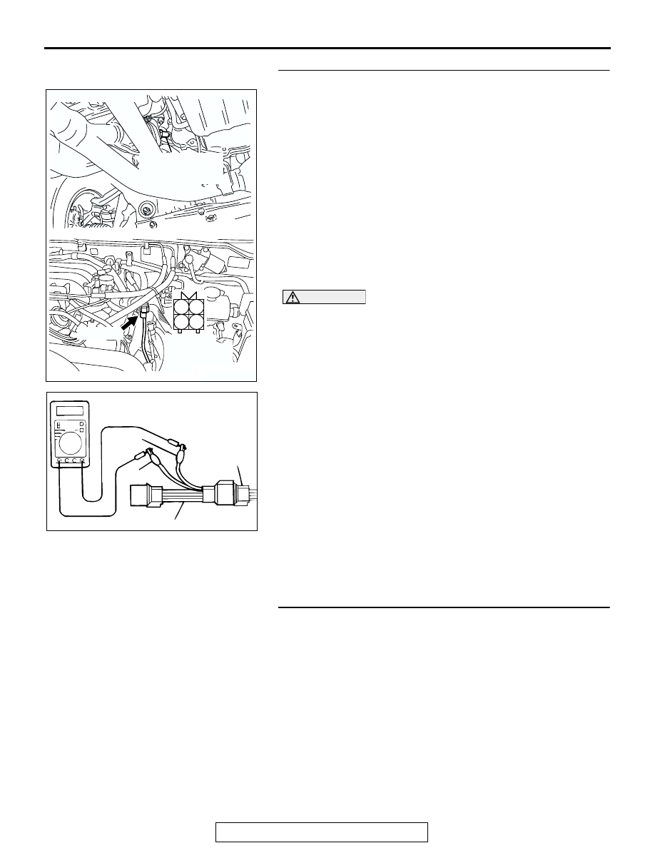
STEP 14. Check the left bank heated oxygen sensor (front).

(1) Disconnect the left bank heated oxygen sensor (front) 

connector B-26 and connect test harness special tool 
MB991316 to the connector on the left bank heated oxygen 
sensor (front) side.

(2) Warm up the engine until engine coolant temperature 

reaches 80

°C (176°F) or higher.

(3) Perform a racing for 5 minutes or more with the engine 

speed of 4,500 r/min.

(4) Connect a digital voltage meter between terminal No. 2 

(black clip of special tool) and terminal No. 4 (white clip of 
special tool).

(5) While repeatedly revving the engine, measure the left bank 

heated oxygen sensor (front) output voltage.

Standard value: 0.6 

 1.0 volt

CAUTION

• Be very careful when connecting the jumper wire; 

incorrect connection can damage the left bank heated 
oxygen sensor (front).

• Be careful the heater is broken when voltage of beyond 

8 volts is applied to the left bank heated oxygen sensor 
(front) heater.
NOTE: If the sufficiently high temperature [of approximate 
400

°

C (752

°

F) or more] is not reached although the left 

bank heated oxygen sensor (front) is normal, the output 
voltage would be possibly low although the rich air/fuel 
ratio. Therefore, if the output voltage is low, use a jumper 
wire to connect the terminal No. 1 (red clip of special tool) 
and the terminal No. 3 (blue clip of special tool) of the left 
bank heated oxygen sensor (front) with the positive terminal 
and the negative terminal of 8 volts power supply respec-
tively, then check again.

Q: Is the voltage between 0.6 and 1.0 volt?

YES : Replace the PCM. Then go to Step 15.
NO :  Replace the left bank heated oxygen sensor (front). 

Then go to Step 15.

STEP 15. Test the OBD-II drive cycle.
(1) Carry out a test drive with the drive cycle pattern. Refer to 

Diagnostic Function 

− OBD-II Drive Cycle − Procedure 6 − 

Other Monitor 

P.13A-4

.

(2) Check the diagnostic trouble code (DTC).
Q: Is DTC P0150 set?

YES : Retry the troubleshooting.
NO :  The inspection is complete.

AK201278

1

2

3

4

CONNECTOR: B-26

B-26(GR)

AC

HARNESS 
CONNECTOR: 
COMPONENT 
SIDE

LEFT BANK
HEATED OXYGEN
SENSOR (FRONT)

AKX01624

HEATED
OXYGEN
SENSOR
COMPONENT
SIDE
CONNECTOR

MB991316

WHITE

BLACK

AN

MULTIPORT FUEL INJECTION (MFI) DIAGNOSIS

TSB Revision

MULTIPORT FUEL INJECTION (MFI)

13A-284

DTC P0151: Heated Oxygen Sensor Circuit Low Voltage (bank 2, sensor 1)

BL

ACK

BL

ACK

BL

ACK

TO PCM

FROM MFI RELAY

WHITE

AK201135

96

108

4

3

1

LEFT BANK
HEATED OXYGEN
SENSOR (FRONT)

POWERTRAIN CONTROL
MODULE (PCM)

11

9

7

2

4

3

1 2

B-26

MU802665

1

12

23 24 25 26

2

13

3

14

4

15

5

16

6

17

7

18

8

19

9

20 21 22

27 28 29 30 31 32 33

10 11

D-116

1
5

7 8

3 4
9 10

2
6

D-14

MU801335

Left Bank Heated Oxygen Sensor (front) Circuit

9192

939495

96979899

100

105

113114

115116117

118119120

106

107108109

110111112

101102103

104

D-135

(MU803805)

AK201277

CONNECTOR: B-26

B-26(GR)

AD

LEFT BANK
HEATED OXYGEN
SENSOR (FRONT)

AK201038AF

CONNECTOR: D-135

PCM

D-135(GR)

AK201049

D-14

AB

CONNECTOR: D-14

MULTIPORT FUEL INJECTION (MFI) DIAGNOSIS

TSB Revision

MULTIPORT FUEL INJECTION (MFI)

13A-285

.

CIRCUIT OPERATION

• A voltage corresponding to the oxygen concen-

tration in the exhaust gas is sent to the PCM (ter-
minal No. 108) from the output terminal (terminal 
No. 4) of the left bank heated oxygen sensor 
(front).

• Terminal No. 2 of the left bank heated oxygen 

sensor (front) is grounded with PCM (terminal 
No. 96).

.

TECHNICAL DESCRIPTION

• The left bank heated oxygen sensor (front) 

detects the concentration of oxygen in the 
exhaust gas; it converts that data to voltage, and 
sends it to the PCM.

• When the left bank heated oxygen sensor (front) 

begins to deteriorate, the heated oxygen sensor 
signal response deteriorates also.

• The PCM varies the air/fuel mixture to make it 

leaner and richer, and checks the response 
speed of the left bank heated oxygen sensor 
(front). In addition, the PCM also checks for an 
open circuit in the left bank heated oxygen sensor 
(front) output line.

.

DESCRIPTIONS OF MONITOR METHODS
Left bank heated oxygen sensor (front) output volt-

age stays low when air/fuel ratio is forced to be 
rich. The above procedure is repeated when oxy-
gen sensor is inactive.

.

MONITOR EXECUTION
Continuous

.

MONITOR EXECUTION CONDITIONS (Other 
monitor and Sensor)

Other Monitor (There is no temporary DTC stored 

in memory for the item monitored below)

• Heated oxygen sensor heater (front) monitor

• Misfire monitor

• Fuel system monitor

Sensor (The sensor below is determined to be 

normal)

• Volume airflow sensor

• Engine coolant temperature sensor

• Intake air temperature sensor

• Barometric pressure sensor

• Throttle position sensor

• Accelerator pedal position sensor

.

AK201049

CONNECTOR: D-116

D-116

AC

MULTIPORT FUEL INJECTION (MFI) DIAGNOSIS

TSB Revision

MULTIPORT FUEL INJECTION (MFI)

13A-286

DTC SET CONDITIONS

Logic Flow Chart

.

Check Conditions

• 3 minutes or more have passed since the engine 

starting sequence was completed.

• Left bank heated oxygen sensor (front) signal 

voltage has continued to be 0.2 volt or lower.

• Engine coolant temperature is higher than 76°C 

(169

°F).

• Engine speed is higher than 1,200 r/min.

• Volumetric efficiency is higher than 25 percent.

• Volume airflow sensor output frequency is higher 

than 100 Hz.

• At least 20 seconds have passed since fuel shut 

off control was canceled.

START

V

F

 > =4.5V

2secs HAS PASSED

YES

YES

YES

NO

NO

NO

MALFUNCTION

MONITORING

CONDITIONS

YES

NO

MONITORING

CONDITIONS

+5V ON

AK302930

V

F

 < 0.2V

10secs HAS PASSED

YES

YES

NO

NO

END

MALFUNCTION

GOOD

MODULATE A/F CONDITION TO RICH


Content   ..  197  198  199  200   ..