Mitsubishi Montero (2004+). Manual - part 179
MULTIPORT FUEL INJECTION (MFI) DIAGNOSIS
TSB Revision
MULTIPORT FUEL INJECTION (MFI)
13A-203
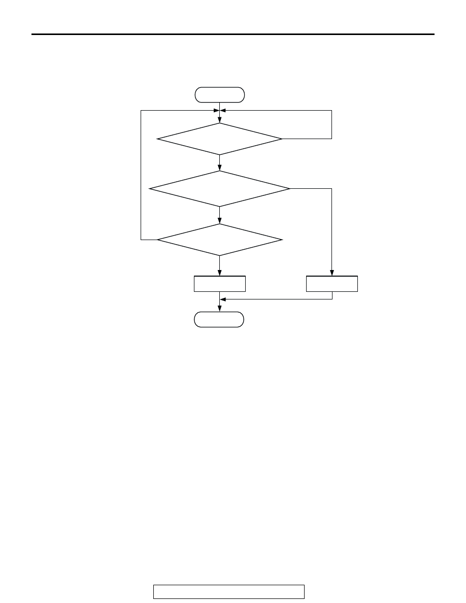
DCT SET CONDITIONS
Logic Flow Chart
.
Check Conditions
• 20 seconds or more have passed since the
engine starting sequence was completed.
• Engine coolant temperature is higher than 76°C
(169
°F).
• Engine speed is higher than 1,200 r/min.
• Volumetric efficiency is between 30 and 80
percent.
• Throttle position sensor output voltage is lower
than 4 volts.
• Except while fuel is being shut off.
• Monitoring time: 30 seconds.
Judgment Criteria
• Right bank heated oxygen sensor (front) output
voltage does not get across 0.5 volt within about
30 seconds.
.
OBD-II DRIVE CYCLE PATTERN
Refer to Diagnostic Function
− OBD-II Drive Cycle −
Procedure 6
.
.
TROUBLESHOOTING HINTS (The most likely
causes for this code to be set are: )
• Right bank heated oxygen sensor (front) deterio-
rated.
• Harness damage in right bank heated oxygen
sensor (front) output line.
• Right bank heated oxygen sensor (rear) deterio-
rated.
NOTE: When the right bank heated oxygen sen-
sor (front) begins to deteriorate, the heated oxy-
gen sensor output voltage will deviate from the
voltage when the sensor was new (normally 0.5
volt at stoichiometric ratio). This deviation will be
corrected by the right bank heated oxygen sensor
(rear).
HEATED OXYGEN SENSOR (FRONT)
OUTPUT VOLTAGE CROSSES 0.5V?
START
END
NO
NO
NO
YES
Yes
YES
MALFUNCTION
GOOD
30secs HAVE PASSED?
MONITORING
CONDITIONS
AK302933