Mitsubishi Montero (2004+). Manual - part 170


  Index      Mitsubishi     Mitsubishi Montero - service repair manual 2004 year


Search            


Content   ..  168  169  170  171   ..


Mitsubishi Montero (2004+). Manual - part 170


MULTIPORT FUEL INJECTION (MFI) DIAGNOSIS

TSB Revision

MULTIPORT FUEL INJECTION (MFI)

13A-167

TROUBLESHOOTING HINTS (The most likely 
causes for this code to be set are: )

• The thermostat is faulty.

• PCM failed.

DIAGNOSIS

STEP 1. Check the cooling system.
Refer to GROUP 14, Engine Cooling Diagnosis 

P.14-2

.

Q: Is the cooling system normal?

YES : Replace the PCM. Then check that the DTC P0128 

does not reset.

NO :  Repair it. Then check that the DTC P0128 does not 

reset.

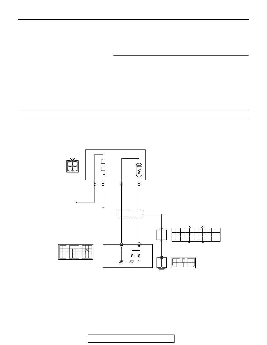
DTC P0130: Heated Oxygen Sensor Circuit (bank 1, sensor 1) 

BL

ACK

BL

ACK

BL

ACK

TO PCM

FROM MFI RELAY

WHITE

AK201131

96

109

4

3

1

RIGHT BANK
HEATED OXYGEN
SENSOR (FRONT)

POWERTRAIN CONTROL
MODULE (PCM)

8

9

7

1 2

4

3

B-07

MU802605

2

1

12

23 24 25 26

2

13

3

14

4

15

5

16

6

17

7

18

8

19

9

20 21 22

27 28 29 30 31 32 33

10 11

D-116

1
5

7 8

3 4
9 10

2
6

D-14

MU801335

Right Bank Heated Oxygen Sensor (front) Circuit

9192

939495

96979899

100

105

113114

115116117

118119120

106

107108109

110111112

101102103

104

D-135

(MU803805)

MULTIPORT FUEL INJECTION (MFI) DIAGNOSIS

TSB Revision

MULTIPORT FUEL INJECTION (MFI)

13A-168

.

CIRCUIT OPERATION

• A voltage corresponding to the oxygen concen-

tration in the exhaust gas is sent to the PCM (ter-
minal No. 109) from the output terminal (terminal 
No. 4) of the right bank heated oxygen sensor 
(front).

• Terminal No. 2 of the right bank heated oxygen 

sensor (front) is grounded with PCM (terminal 
No. 96).

.

TECHNICAL DESCRIPTION

• The right bank heated oxygen sensor (front) 

detects the concentration of oxygen in the 
exhaust gas; it converts those data to voltage, 
and inputs the resulting signals to the PCM.

• When the right bank heated oxygen sensor 

(front) begins to deteriorate, the heated oxygen 
sensor signal response becomes poor.

• The PCM forcibly varies the air/fuel mixture to 

make it leaner and richer, and checks the 
response speed of the right bank heated oxygen 
sensor (front). In addition, the PCM also checks 
for an open circuit in the right bank heated oxy-
gen sensor (front) output line.

.

DESCRIPTIONS OF MONITOR METHODS
 Right bank heated oxygen sensor (front) circuit is 

switched to 5 volts intentionally when oxygen 
sensor output is low, and detects the malfunction 
if the output voltage changes to equal or greater 
than 4.5 volts. The above procedure is repeated 
when oxygen sensor is inactive.

.

MONITOR EXECUTION
Continuous

.

AK201273

CONNECTOR: B-07

B-07(B)

AB

RIGHT BANK
HEATED OXYGEN
SENSOR (FRONT)

AK201038AF

CONNECTOR: D-135

PCM

D-135(GR)

AK201049

D-14

AB

CONNECTOR: D-14

AK201049

CONNECTOR: D-116

D-116

AC

MULTIPORT FUEL INJECTION (MFI) DIAGNOSIS

TSB Revision

MULTIPORT FUEL INJECTION (MFI)

13A-169

MONITOR EXECUTION CONDITIONS (Other 
monitor and Sensor)

Other Monitor (There is no temporary DTC stored 

in memory for the item monitored below)

• Heated oxygen sensor heater (front) monitor

• Misfire monitor

• Fuel system monitor

Sensor (The sensor below is determined to be 

normal)

• Volume airflow sensor

• Engine coolant temperature sensor

• Intake air temperature sensor

• Barometric pressure sensor

• Accelerator pedal position sensor

.

MULTIPORT FUEL INJECTION (MFI) DIAGNOSIS

TSB Revision

MULTIPORT FUEL INJECTION (MFI)

13A-170

DTC SET CONDITIONS

Logic Flow Chart

.

Check Conditions

• 3 minutes or more have passed since the engine 

starting sequence was completed.

• Right bank heated oxygen sensor (front) signal 

voltage has continued to be 0.2 volt or lower.

• Engine coolant temperature is higher than 76°C 

(169

°F).

• Engine speed is higher than 1,200 r/min.

• Volumetric efficiency is higher than 25 percent.

• Monitoring time: 7 seconds.

START

V

F

 > =4.5V

2secs HAS PASSED

YES

YES

YES

NO

NO

NO

MALFUNCTION

MONITORING

CONDITIONS

YES

NO

MONITORING

CONDITIONS

+5V ON

AK302930

V

F

 < 0.2V

10secs HAS PASSED

YES

YES

NO

NO

END

MALFUNCTION

GOOD

MODULATE A/F CONDITION TO RICH


Content   ..  168  169  170  171   ..