Mitsubishi Montero (2004+). Manual - part 154
MULTIPORT FUEL INJECTION (MFI) DIAGNOSIS
TSB Revision
MULTIPORT FUEL INJECTION (MFI)
13A-103
TECHNICAL DESCRIPTION
• The intake air temperature sensor converts the
intake air temperature to a voltage.
• The PCM checks whether this voltage is within a
specified range.
.
DESCRIPTIONS OF MONITOR METHODS
Intake air temperature sensor output voltage is out of
specified range.
.
MONITOR EXECUTION
Continuous
.
MONITOR EXECUTION CONDITIONS (Other
monitor and Sensor)
Other Monitor (There is no temporary DTC stored
in memory for the item monitored below)
• Not applicable
Sensor (The sensor below is determined to be
normal)
• Not applicable
.
DTC SET CONDITIONS
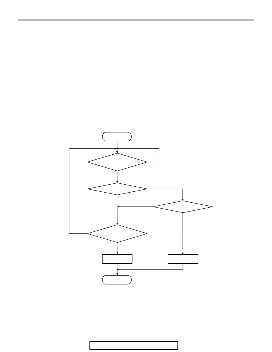
Logic Flow Chart
Check Conditions
• 2 seconds or more have passed since the start-
ing sequence was completed.
Judgement Criteria
• Intake air temperature sensor output voltage has
continued to be 0.2 volt or lower [corresponding
to an air intake temperature of 115
°C (239°F) or
higher] for 2 seconds.
.
START
OUTPUT VOLTAGE < 0.2V
END
NO
NO
NO
YES
YES
YES
MALFUNCTION
GOOD
CONTINUOUS
FAILURE FOR 2secs
OUTPUT VOLTAGE > 4.6V
MONITORING
CONDITIONS
NO
YES
AK302922