Mitsubishi Montero (2004+). Manual - part 137
MULTIPORT FUEL INJECTION (MFI) DIAGNOSIS
TSB Revision
MULTIPORT FUEL INJECTION (MFI)
13A-35
DTC SET CONDITIONS <Range/Performance problem
− high input>
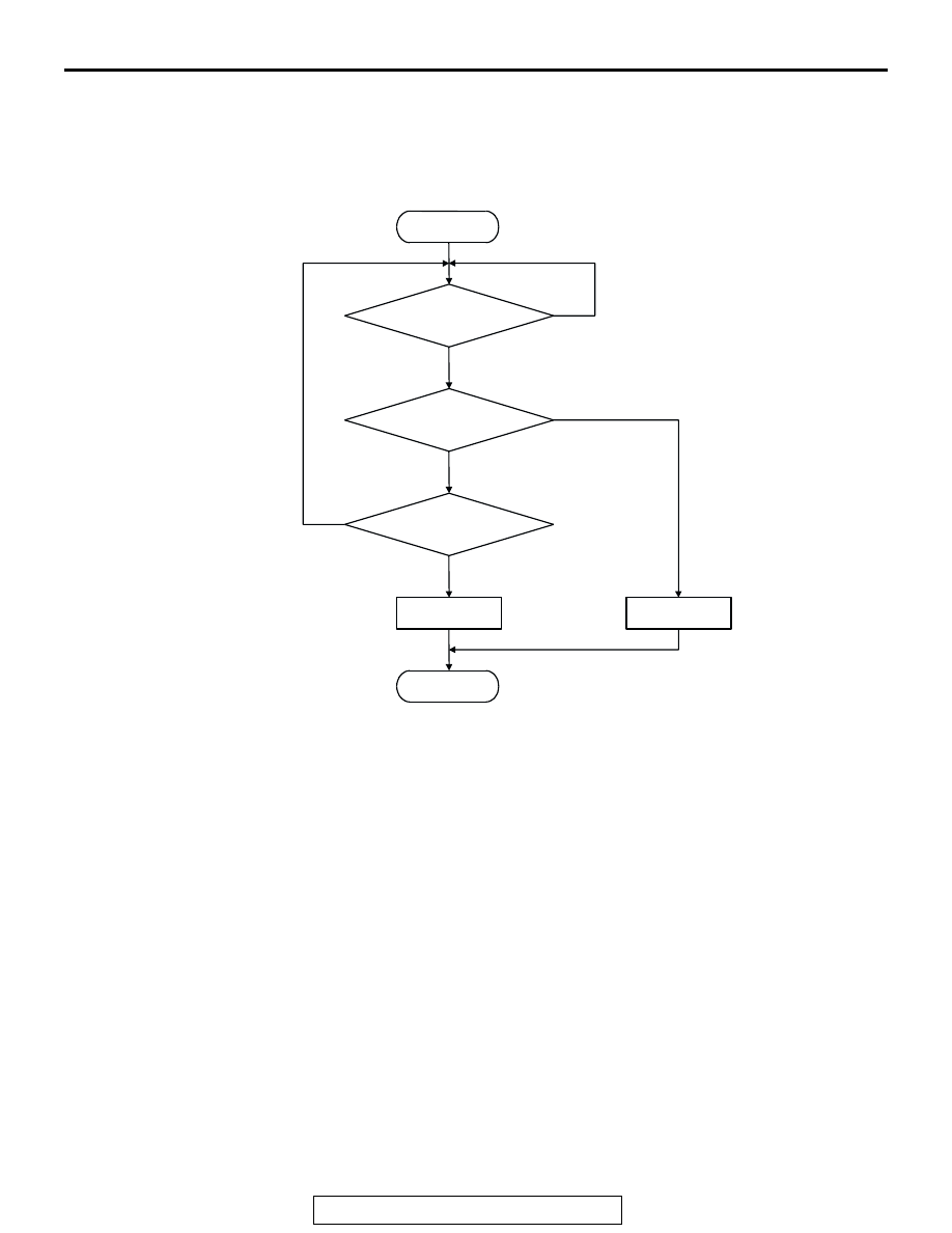
Logic Flow Chart
Check Conditions
• Throttle position sensor output voltage is 1.5 volts
or higher.
• Engine speed is higher than 2,000 r/min.
Judgement Criteria
• Volume airflow sensor output frequency has con-
tinued to be 60 Hz or lower for 2 seconds.
.
START
Monitoring
Conditions
END
No
Yes
No
Yes
No
Yes
Malfunction
Good
Output Frequency
> = 800Hz
Continuous
Failure for 2secs
AK302693