Mitsubishi Montero (2004+). Manual - part 131
MULTIPORT FUEL INJECTION (MFI) DIAGNOSIS
TSB Revision
MULTIPORT FUEL INJECTION (MFI)
13A-11
CAUTION
To prevent damage to scan tool MB991958, always turn the
ignition switch to the "LOCK" (OFF) position before con-
necting or disconnecting scan tool MB991958.
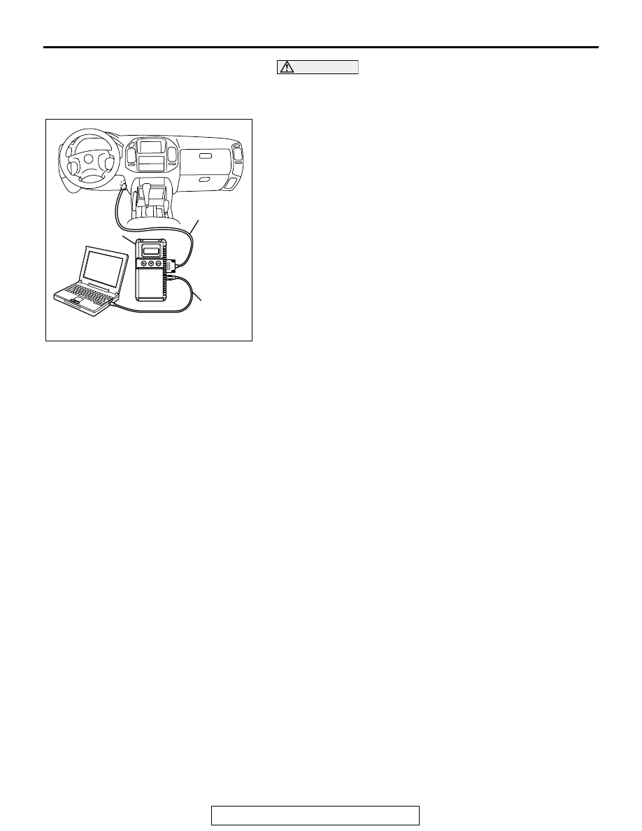
1. Connect scan tool MB991958 to the data link connector.
2. Turn the ignition switch to the "ON" position.
3. Select "Interactive Diagnosis" from the start-up screen.
4. Select "System select."
5. Choose "MFI" from the "POWER TRAIN" tab.
6. Select "MITSUBISHI."
7. Select "Actuator Test."
8. Choose an appropriate item and select the "OK" button.
PROVISIONAL DTCs [MUT-III OBD-II Test Mode -
Results (Mode 7)]
The scan tool MB991958 (MUT-III Sub Assembly) will display
the Provisional DTCs reported by PCM if the PCM detects
some malfunction for "Misfire", "Fuel System" and "Compre-
hensive" monitoring during a SINGLE Driving Cycle. The
intended use of this data is to assist the technician after a vehi-
cle repair, and after clearing diagnostic information, by report-
ing test result after a SINGLE Driving Cycle. Note that the test
results reported by this mode do not necessarily indicate a
faulty component/system. If test results indicate a failure after
ADDITIONAL (consecutive) driving, then the Malfunction Indi-
cator Lamp (SERVICE ENGINE SOON) will be illuminated and
a DTC will set.
AK302970
AB
MB991911
MB991824
MB991827