Mitsubishi Montero (2004+). Manual - part 1216


  Index      Mitsubishi     Mitsubishi Montero - service repair manual 2004 year


Search            


Content   ..  1214  1215  1216  1217   ..


Mitsubishi Montero (2004+). Manual - part 1216


SRS AIR BAG DIAGNOSIS

TSB Revision

SUPPLEMENTAL RESTRAINT SYSTEM (SRS)

52B-199

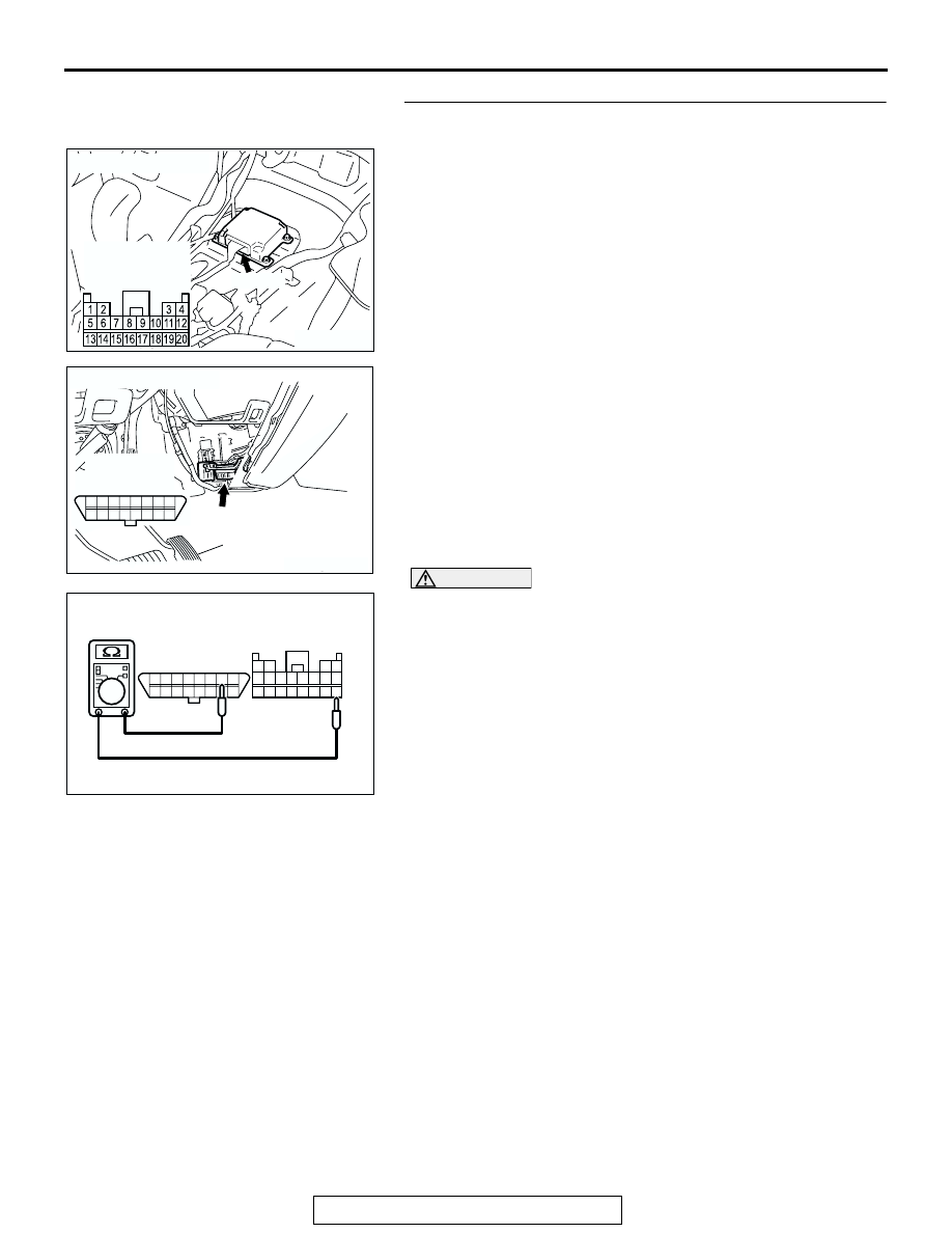
STEP 2. Check the communication line between the 
SRS-ECU and the scan tool.
(1) Disconnect SRS-ECU connector E-08 and data link 

connector D-118 and measure at the wiring harness side. 

CAUTION

Do not insert a test probe into the terminal of the SRS-ECU 
connector E-08 from its front side directly as the connector 
contact pressure may be weakened.
(2) Check for continuity between the following terminals.

Between connector E-08 terminal 20 and connector D-118 
terminal 7
It should be less than 2 ohms.

Q: Does continuity exist?

YES : Go to Step 3.
NO :  Go to Step 5.

ACX01478AM

CONNECTOR: E-08

E-08 (Y)

HARNESS SIDE
CONNECTOR
(REAR VIEW)

AC204695

CONNECTOR : D-118

AC

D-118 (B)

ACCELLATOR PEDAL

1 2 3 4 5 6 7 8
9 10 11121314 15 16

D-118 
CONNECTOR
(FRONT VIEW)

1314151617181920

5 6 7 8 9 101112

1 2

3 4

1 2 3 4 5 6 7 8

9 10111213141516

AC006263

D-118 
CONNECTOR
(FRONT VIEW)

E-08 HARNESS SIDE
CONNECTOR 
(REAR VIEW)

AL

SRS AIR BAG DIAGNOSIS

TSB Revision

SUPPLEMENTAL RESTRAINT SYSTEM (SRS)

52B-200

STEP 3. Check the ground circuit to the SRS-ECU.
(1) Disconnect SRS-ECU connector E-08, and measure at the 

wiring harness side.

CAUTION

Do not insert a test probe into the terminal from its front 
side directly as the connector contact pressure may be 
weakened.

(2) Check for continuity between E-08 harness terminal 7 and 

body ground.
It should be less than 2 ohms.

Q: Does continuity exist?

YES : Go to Step 4.
NO :  Go to Step 6.

STEP 4. Check the power supply circuit to the SRS-ECU.
(1) Disconnect SRS-ECU connector E-08, and measure at the 

wiring harness side.

(2) Connect the negative battery terminal.
(3) Turn the ignition switch to the "ON" position.

CAUTION

Do not insert a test probe into the terminal from its front 
side directly as the connector contact pressure may be 
weakened.
(4) Measure the voltage between terminals 13, 16 and body 

ground.
Voltage should measure 9 volts or more.

Q: Is the measured voltage within the specified range?

YES : Recheck the trouble symptom. If it is not solved, 

replace the SRS-ECU (Refer to 

P.52B-215

). Then go 

to Step 8.

NO :  Go to Step 7.

ACX01478AM

CONNECTOR: E-08

E-08 (Y)

HARNESS SIDE
CONNECTOR
(REAR VIEW)

AC201527

9 10 11 12

13 1415 16

1 2

3 4

5 6 7 8

17 18 19 20

E-08 HARNES SIDE
CONNECTOR 
(REAR VIEW)

AK

ACX01478AM

CONNECTOR: E-08

E-08 (Y)

HARNESS SIDE
CONNECTOR
(REAR VIEW)

AC006265

13 14 15 16 17 18 19 20

5 6 7 8 9 10 11 12

1 2

3 4

AQ

E-08 HARNESS SIDE
CONNECTOR
(REAR VIEW)

SRS AIR BAG DIAGNOSIS

TSB Revision

SUPPLEMENTAL RESTRAINT SYSTEM (SRS)

52B-201

STEP 5. Check the harness wires between SRS-ECU 
connector E-08 (terminal No.20) and data link connector 
D-118 (terminal No.7).

NOTE: After inspecting intermediate connector D-29 inspect 
the wiring harness. If the intermediate connector D-29 is dam-
aged, repair or replace it (Refer to GROUP 00E, Harness Con-
nector Inspection 

P.00E-2

).. Then go to Step 8.

Q: Are the harness wires between SRS-ECU connector 

E-08 (terminal No.20) and data link connector D-118 
(terminal No.7) in good condition?
YES : 
Go to step 8.
NO :  Repair the harness wires between SRS-ECU 

connector E-08 and data link connector D-118. Then 
go to Step 8.

ACX01478AM

CONNECTOR: E-08

E-08 (Y)

HARNESS SIDE
CONNECTOR
(REAR VIEW)

AC204695

CONNECTOR : D-118

AC

D-118 (B)

ACCELLATOR PEDAL

1 2 3 4 5 6 7 8
9 10 11121314 15 16

D-118 
CONNECTOR
(FRONT VIEW)

AC204231AF

CONNECTOR : D-29

D-29

D-29

33

22

11

28

17

16

15

14

13

12

25

23 24

26 27

3

1 2

4 5

21

20

19

18
29 30

32

31

7

6

8

10

9

SRS AIR BAG DIAGNOSIS

TSB Revision

SUPPLEMENTAL RESTRAINT SYSTEM (SRS)

52B-202

STEP 6. Check the harness wire between SRS-ECU 
connector E-08 (terminal No.7) and ground.
Q: Is the harness wire between SRS-ECU connector E-08 

(terminal No.7) and ground in good condition?
YES : 
Go to Step 8.
NO :  Repair the harness wire between SRS-ECU 

connector E-08 and ground. Then go to Step 8.

STEP 7. Check the harness wires between SRS-ECU 
connector E-08 (terminal No.13 and 16) and ignition switch 
connector D-204 (terminal No.2).

ACX01478AM

CONNECTOR: E-08

E-08 (Y)

HARNESS SIDE
CONNECTOR
(REAR VIEW)

ACX01508

GROUND

AE

ACX01478AM

CONNECTOR: E-08

E-08 (Y)

HARNESS SIDE
CONNECTOR
(REAR VIEW)

AC204226AG

CLOCK SPRING

CONNECTOR: D-204

D-204

HARNESS 
SIDE 
CONNECTOR
(FRONT VIEW)

2
5

6

3

4

1


Content   ..  1214  1215  1216  1217   ..