Mitsubishi Montero (2004+). Manual - part 119


  Index      Mitsubishi     Mitsubishi Montero - service repair manual 2004 year


Search            


Content   ..  117  118  119  120   ..


Mitsubishi Montero (2004+). Manual - part 119


CYLINDER HEAD AND VALVES

TSB Revision

ENGINE OVERHAUL

11B-35

3. Before fitting the valve seat, either heat the cylinder head up 

to approximately 250

°C (482°F) or cool the valve seat in 

liquid nitrogen, to prevent the cylinder head bore from 
galling.

4. Using a valve seat cutter, correct the valve seat to the 

specified width and angle. Using a valve seat cutter, correct 
the valve seat to the specified width and angle. See "VALVE 
SEAT RECONDITIONING PROCEDURE" on the previous 
page.

.

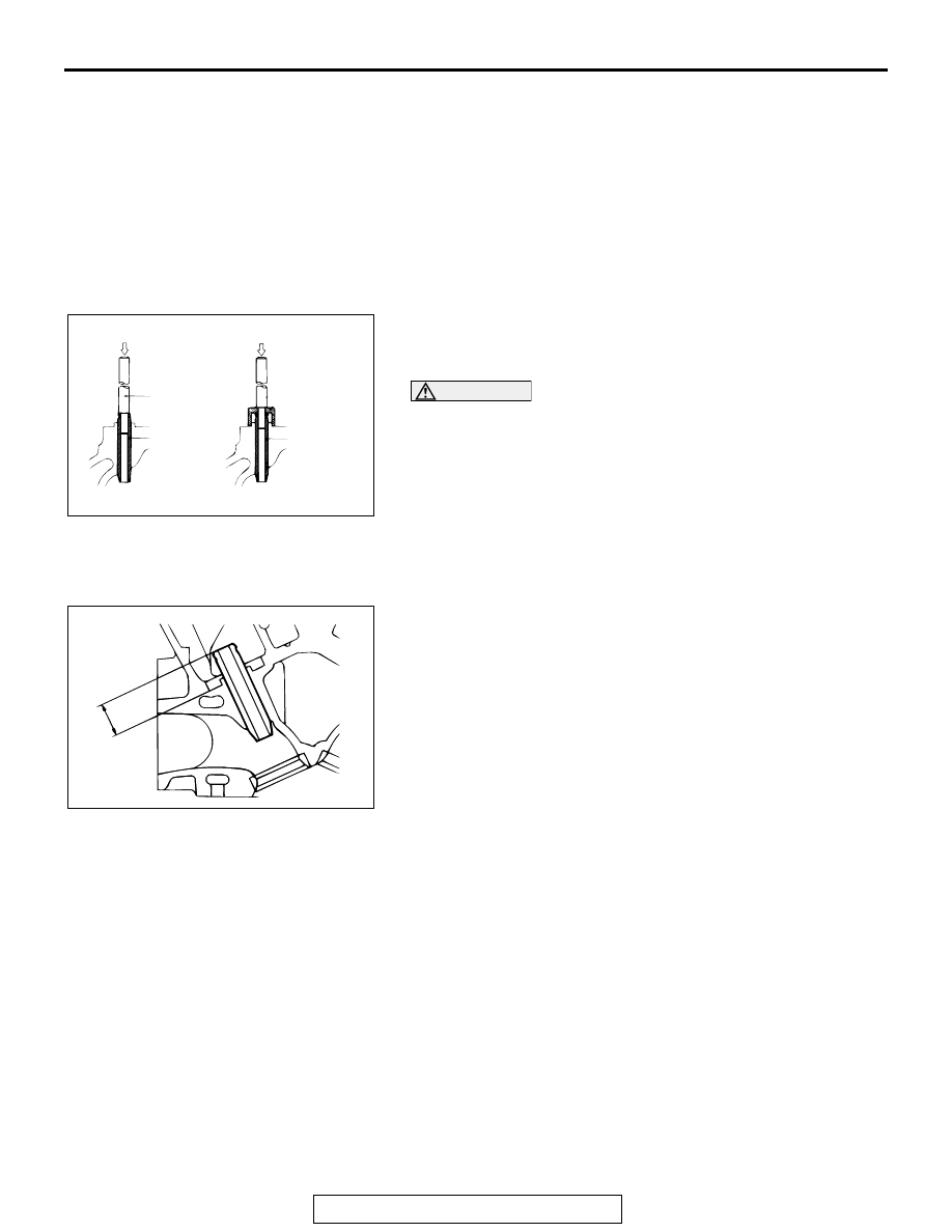
VALVE GUIDE REPLACEMENT PROCEDURE
1. Remove the snap ring from the exhaust valve guide.
2. Using a press, remove the valve guide toward the cylinder 

head gasket surface.

CAUTION

Do not install a valve guide of the same size again.
3. Re bore the valve guide hole of the cylinder head so that it 

fits the press-fitted oversize valve guide.

Valve guide hole diameter:

0.05 oversize 11.05 

 11.07 mm (0.4350  0.4358 inch)

0.25 oversize 11.25 

 11.27 mm (0.4429  0.4457 inch)

0.50 oversize 11.50 

 11.52 mm (0.4528  0.4535 inch)

4. Install the new snap ring into the groove of exhaust valve 

guide.

5. Press-fit the valve guide until it protrudes 14 mm (0.55 inch) 

from the cylinder head top surface as shown in the 
illustration.

NOTE: When press-fitting the valve guide, work from the cylin-
der head top surface.
NOTE: After installing the valve guides, insert new valves in 
them to check for sliding condition.

AKX00712

REMOVAL

INSTALLATION

PRESS

PRESS

PUSH ROD

VALVE 
GUIDE

VALVE 
GUIDE

AB

AKX00727

14 mm 
(0.55 in)

AB

OIL PAN AND OIL PUMP

TSB Revision

ENGINE OVERHAUL

11B-36

OIL PAN AND OIL PUMP

REMOVAL AND INSTALLATION

M1113008100367

Required Special Tool

• MD998717: Crankshaft Front Oil Seal Installer

AK201079

1

2

3

4

5

6

7

8

9

10

12

13

14

15

16

17

18

19

20

11

23 ± 3 N·m
17 ± 2 ft-lb

39 ± 5 N·m
29 ± 4 ft-lb

19 ± 3 N·m
14 ± 2 ft-lb

44 ± 5 N·m
33 ± 4 ft-lb

10 ± 2 N·m
87 ± 17 in-lb 

14 ± 1 N·m
124 ± 9 in-lb

9 ± 3 N·m
80 ± 26 in-lb

10 ± 2 N·m
87 ± 17 in-lb 

11 ± 1 N·m
97 ± 9 in-lb

11 ± 1N·m
97 ± 9 in-lb

AB

APPLY ENGINE OIL
TO ALL MOVING
PARTS BEFORE
INSTALLATION.

54 ± 5 N·m
40 ± 4 ft-lb

21

14 ± 1 N·m
124 ± 9 in-lb

9 ± 3 N·m
80 ± 26 in-lb

9 ± 3 N·m
80 ± 26 in-lb

REMOVAL STEPS

>>F<<

1. ENGINE OIL PRESSURE SWITCH
2. OIL COOLER BY-PASS VALVE

>>E<<

3. OIL FILTER
4. OIL FILTER BRACKET
5. OIL FILTER BRACKET GASKET
6. DRAIN PLUG

>>D<<

7. DRAIN PLUG GASKET
8. COVER

<<A>> >>C<<

9. OIL PAN
10. BAFFLE PLATE
11. OIL SCREEN

12. OIL SCREEN GASKET
13. RELIEF PLUG
14. RELIEF SPRING
15. RELIEF PLUNGER

>>B<<

16. CRANKSHAFT OIL SEAL
17. OIL PUMP CASE
18. OIL PUMP CASE GASKET
19. OIL PUMP COVER

<<B>> >>A<<

20 OIL PUMP OUTER ROTOR

<<B>> >>A<<

21. OIL PUMP INNER ROTOR

REMOVAL STEPS (Continued)

OIL PAN AND OIL PUMP

TSB Revision

ENGINE OVERHAUL

11B-37

REMOVAL SERVICE POINTS

.

<<A>> OIL PAN REMOVAL
1. Remove the bolts A shown in the illustration first.
2. Remove all other bolts.

CAUTION

Do not use a scraper or special tool to remove the oil pan.
3. Remove the oil pan.

4. Thread the bolt into the illustrated bolt hole to remove the oil 

pan.

.

<<B>> OUTER ROTOR/INNER ROTOR REMOVAL
Make alignment dots on the outer and inner rotors for assem-
bly.

INSTALLATION SERVICE POINTS

.

>>A<< INNER ROTOR/OUTER ROTOR INSTALLATION
Apply engine oil to the rotors. Then, install the rotors ensuring 
that the alignment dots made at disassembly are properly 
aligned.

.

AKX01450 AB

TIMING BELT SIDE

A

AKX01451

ENGINE REAR SIDE

AB

AKX00742AB

ALIGNMENT DOTS

AKX00742AB

ALIGNMENT DOTS

OIL PAN AND OIL PUMP

TSB Revision

ENGINE OVERHAUL

11B-38

>>B<< CRANKSHAFT OIL SEAL INSTALLATION 
1. Install the guide of special tool MD998717 to the front end of 

the crankshaft.

2. Apply engine oil to the lip area of a new oil seal and push it 

in until it contacts the oil pump case.

3. Using special tool MD998717, press-fit the oil seal into the 

oil pump case.

.

>>C<<OIL PAN INSTALLATION
1. Clean the gasket surfaces of the cylinder block and upper oil 

pan.

CAUTION

When installing the upper oil pan, be sure not to expel the 
sealant from the oil pan flange at portion A in the illustra-
tion.
2. Apply a 4 mm (0.2 inch) diameter bead of sealant Mitsubishi 

Genuine Parts number MD970389, or equivalent to the oil 
pan. Be sure to install the oil pan quickly while the sealant is 
wet.
NOTE: Install the oil pan within 15 minutes after applying liq-
uid gasket.
NOTE: Then wait at least one hour. Never start the engine 
or let engine oil or coolant touch the adhesion surface during 
that time.

3. Tighten the upper oil pan bolts in the sequence shown.

Tightening torque: 9 

± 3 Nm (80 ± 26 in-lb)

4. After installation, keep the sealed area away from the oil and 

coolant for approximately one hour.

.

AKX00659 AB

MD998717 (GUIDE)

OIL SEAL

AKX00660

MD998717

AB

AKX01403AB

LIQUID GASKET APPLICATION AREA

(TOP VIEW)

A

AKX01404AC

1

5

11

14

15

10

6

2

3

7

12

16

9

13

8

4

FLANGE BOLT TIGHTENING

SEQUECE(BOTTOM VIEW)


Content   ..  117  118  119  120   ..