Mitsubishi Montero (2004+). Manual - part 118
CYLINDER HEAD AND VALVES
TSB Revision
ENGINE OVERHAUL
11B-31
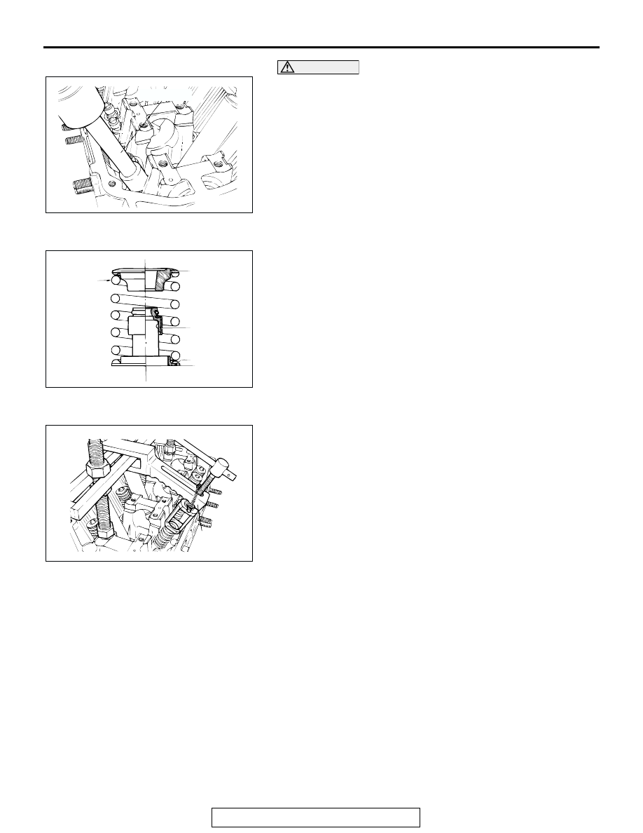
CAUTION
Always use the special tool to install the valve stem seal.
Improperly installed valve stem seals may leak oil.
2. Using special tool MD998774, install a new stem seal to the
valve guide.
.
>>B<< VALVE SPRING INSTALLATION
Install the valve spring end with its identification color toward
the spring retainer.
.
>>C<< RETAINER LOCK INSTALLATION
Using special tool MD998772, compress the valve spring and
insert the retainer lock into position.
.
AKX00618AB
MD998774
AKX00718
SPRING SEAT
SPRING
RETAINER
IDENTIFI-
CATION
COLOR
STEM SEAL
AB
AKX00617
MD998772
AB