Mitsubishi Montero (2004+). Manual - part 1147


  Index      Mitsubishi     Mitsubishi Montero - service repair manual 2004 year


Search            


Content   ..  1145  1146  1147  1148   ..


Mitsubishi Montero (2004+). Manual - part 1147


ON-VEHICLE SERVICE

TSB Revision

ENGINE COOLING

14-7

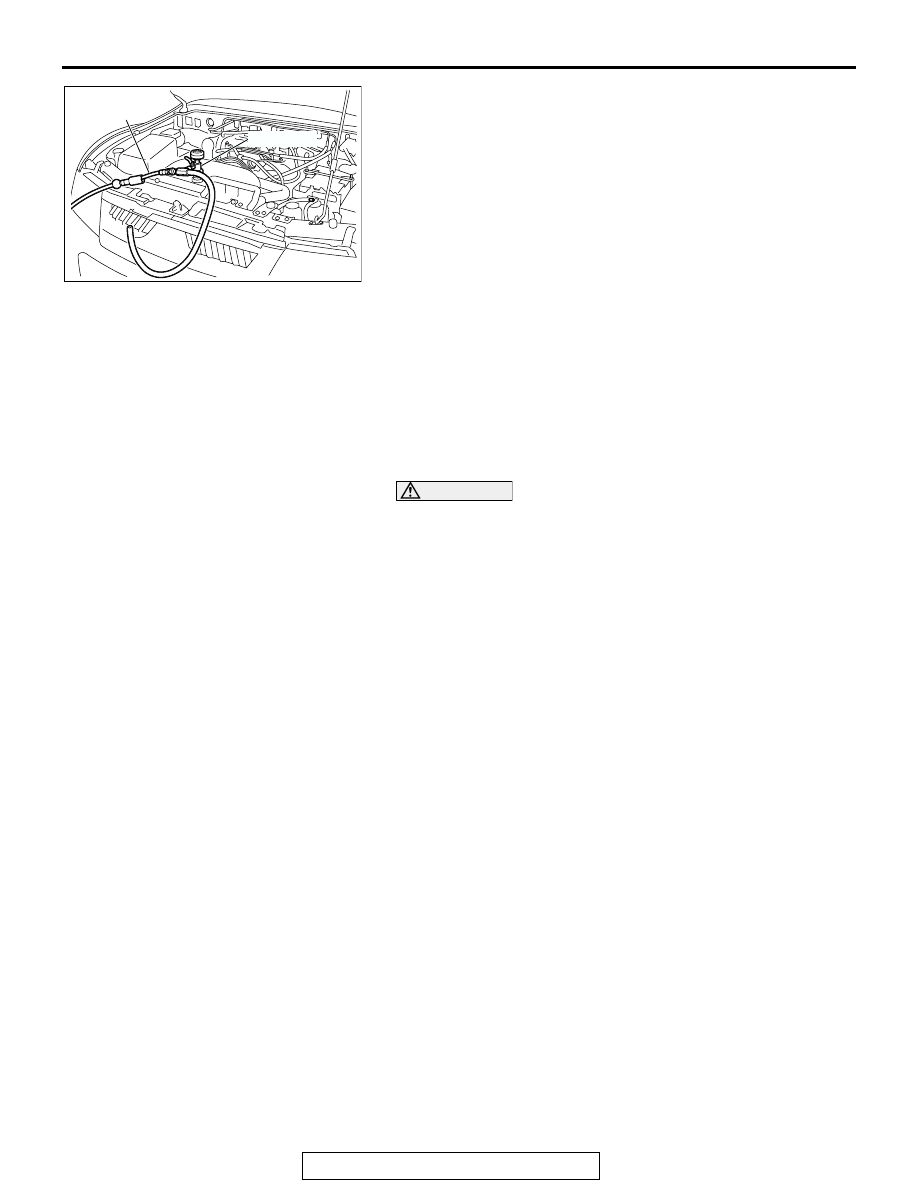
9. <When special tool MB991871 is used>

By referring to the section on coolant, select an appropriate 
concentration for safe operating temperature within the 
range of 30 to 60 %. Use special tool MB991871 to refill the 
coolant. A convenient mixture is a 50 % water and 50 % 
antifreeze solution [freezing point: 

−31°C (−32.8 °F)].

NOTE: For how to use special tool MB991871, refer to its 
manufacturer’s instructions.

Recommended antifreeze:
Long life antifreeze coolant or an equivalent

Quantity: 9.0 dm

3

 (9.5 quarts)

10.Reinstall the radiator cap.
11.Start the engine and let it warm up until the thermostat 

opens.

12.After repeatedly revving the engine up to 3,000 r/min 

several times, then stop the engine.

13.Remove the radiator cap after the engine has become cold, 

and pour in coolant up to the brim. Reinstall the cap.

CAUTION

Do not overfill the reserve tank.
14.Add coolant to the reserve tank between the "FULL" and 

"LOW" mark if necessary.

ENGINE COOLANT CONCENTRATION TEST

M1141001100277

Refer to GROUP 00, RECOMMENDED LUBRICANTS AND 
LUBRICANT CAPACITIES TABLE 

P.00-33

.

DRIVE BELT TENSION CHECK AND 
ADJUSTMENT

M1141004500100

Refer to GROUP 00, Maintenance Service 

P.00-41

.

AC204032

AB

AIR HOSE

MB991871

RADIATOR

TSB Revision

ENGINE COOLING

14-8

RADIATOR

REMOVAL AND INSTALLATION

M1141001500543

Pre-removal Operation
• Engine Coolant Draining (Refer to 

P.14-6

.)

• Air Intake Duct Removal (Refer to GROUP 15 

P.15-6

.)

Post-installation Operation
• Engine Coolant Refilling and Level Check (Refer to 

P.14-6

.)

• Transmission Fluid Refilling and Level Check (Refer to 

GROUP 00, Maintenance Service 

P.00-43

.)

• Air Intake Duct Installation (Refer to GROUP 15 

P.15-6

.)

ACX00403AB

5.0 ± 1.0 N·m
44 ± 9 in-lb

12 ± 2 N·m
101 ± 23 in-lb

7

9

4

8

10

3

11

5

6

1

2

REMOVAL STEPS

<<A>> >>B<<

1.

RADIATOR SHROUD UPPER 
COVER

<<A>> >>B<<

2.

RADIATOR SHROUD LOWER 
COVER

<<B>>

3.

TRANSMISSION FLUID COOLER 
HOSE CONNECTION

<<C>> >>A<<

4.

RADIATOR UPPER HOSE

<<C>> >>A<<

5.

RADIATOR LOWER HOSE

6.

SHROUD

7.

OVERFLOW HOSE

8.

CONDENSER TANK

9.

UPPER INSULATOR

10. RADIATOR
11. LOWER INSULATOR

REMOVAL STEPS (Continued)

RADIATOR

TSB Revision

ENGINE COOLING

14-9

REMOVAL SERVICE POINTS

.

<<A>> RADIATOR SHROUD UPPER COVER/RADIATOR 
SHROUD LOWER COVER REMOVAL

CAUTION

Be careful not to break or bend the fixing lever by tilting it 
outward too excessively.
Tilt the fixing lever at the shroud housing cover outward slightly, 
and remove the cover toward the fan axis from its four fixing 
points. 

.

<<B>> A/T OIL COOLER HOSE REMOVAL
After removing the hose from the radiator, plug the hose and 
the radiator nipple to prevent dust or foreign particles from get-
ting in.

.

<<C>> RADIATOR UPPER HOSE/RADIATOR LOWER HOSE 
DISCONNECTION
Make mating marks on the radiator hose and the hose clamp. 
Disconnect the radiator hose.

INSTALLATION SERVICE POINTS

.

>>A<< RADIATOR LOWER HOSE/RADIATOR UPPER HOSE 
CONNECTION
1. Insert each hose as far as the projection of the water inlet 

fitting.

2. Align the mating marks on the radiator hose and hose 

clamp, and then connect the radiator hose.

.

AC200641AB

MATING MARKS

AC200642

MATING
MARKS

PROJECTION

WATER OUTLET
FITTING

AB

COOLING FAN

TSB Revision

ENGINE COOLING

14-10

>>B<< RADIATOR SHROUD UPPER COVER/RADIATOR 
SHROUD LOWER COVER INSTALLATION
1. Install the covers securely until the click can be heard from 

the four fixing points.

2. Two lugs around the circumference of the covers should be 

seen on the outside of the shroud.

3. After installation, check that the covers are fixed securely.

COOLING FAN

REMOVAL AND INSTALLATION

M1141002100106

ACX00404 AC

AC204071

1

2

3

4

5 6

AB

11 ± 1 N·m
93 ± 13 in-lb

11 ± 1 N·m
93 ± 13 in-lb

REMOVAL STEPS

>>B<<

1.

RADIATOR SHROUD UPPER 
COVER

<<A>> >>A<<

2.

DRIVE BELT

3.

COOLING FAN AND FAN 
CLUTCH ASSEMBLY

4.

FAN PULLEY

5.

COOLING FAN

6.

FAN CLUTCH

REMOVAL STEPS (Continued)


Content   ..  1145  1146  1147  1148   ..