Mitsubishi Montero (2004+). Manual - part 1145


  Index      Mitsubishi     Mitsubishi Montero - service repair manual 2004 year


Search            


Content   ..  1143  1144  1145  1146   ..


Mitsubishi Montero (2004+). Manual - part 1145


FUEL TANK

TSB Revision

FUEL SUPPLY

13B-13

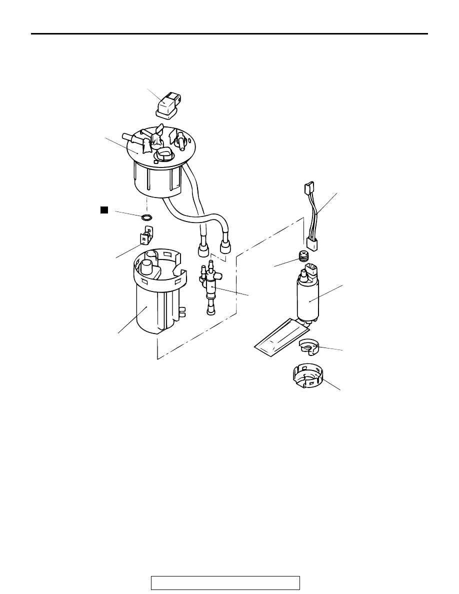
FUEL PUMP (MODULE) DISASSEMBLY AND ASSEMBLY

M1135004600023

ASSEMBLY SERVICE POINT

.

>>A<< O-RING / GROMMET INSTALLATION
Apply gasoline on the O-ring and the grommet before mounting 
them to prevent damage or twisting.

ACX01537

10

11

9

8

6

7

4

5

3

2

1

AB

N

DISASSEMBLY STEPS

1. FUEL PUMP BRACKET
2. FUEL PUMP CUSHION
3. FUEL PUMP

>>A<<

4. GROMMET
5. PUMP HARNESS
6. HOUSING

7. ASSIST PUMP
8. CAP

>>A<<

9. O-RING
10. FUEL TANK DIFFERENTIAL 

PRESSURE SENSOR

11. FUEL HIGH-PRESSURE FILTER

DISASSEMBLY STEPS (Continued)

SPECIFICATIONS

TSB Revision

FUEL SUPPLY

13B-14

SPECIFICATIONS

FASTENER TIGHTENING SPECIFICATION

M1135003900258

SERVICE SPECIFICATION

M1135000300031

ITEMS

SPECIFICATIONS

Fuel level sensor

2.5 

± 0.4 N⋅m (22 ± 4 in-lb)

Fuel pump module

2.5 

± 0.4 N⋅m (22 ± 4 in-lb)

Fuel tank drain plug

21 

± 4 N⋅m (16 ± 2 ft-lb)

Fuel tank mounting nut

26 

± 4 N⋅m (19 ± 3 ft-lb)

Fuel tank rollover valve

2.5 

± 0.4 N⋅m (22 ± 4 in-lb)

Fuel tank leveling valve assembly

2.5 

± 0.4 N⋅m (22 ± 4 in-lb)

ITEM

STANDARD VALUE

Fuel tank differential pressure sensor output voltage V

2.0 

− 3.0

14-1

GROUP 14

ENGINE COOLING

CONTENTS

GENERAL DESCRIPTION. . . . . . . . .

14-2

SPECIAL TOOL . . . . . . . . . . . . . . . . .

14-2

ENGINE COOLING DIAGNOSIS . . . .

14-2

INTRODUCTION. . . . . . . . . . . . . . . . . . . . . 

14-2

TROUBLESHOOTING STRATEGY . . . . . . 

14-2

SYMPTOM CHART. . . . . . . . . . . . . . . . . . . 

14-2

SYMPTOM PROCEDURES . . . . . . . . . . . . 

14-3

ON-VEHICLE SERVICE. . . . . . . . . . .

14-5

ENGINE COOLANT LEAK CHECK  . . . . . . 

14-5

RADIATOR CAP PRESSURE CHECK. . . . 

14-5

ENGINE COOLANT REPLACEMENT  . . . . 

14-6

ENGINE COOLANT CONCENTRATION 
TEST . . . . . . . . . . . . . . . . . . . . . . . . . . . . . . 

14-7

DRIVE BELT TENSION CHECK AND 
ADJUSTMENT  . . . . . . . . . . . . . . . . . . . . . . 

14-7

RADIATOR. . . . . . . . . . . . . . . . . . . . .

14-8

REMOVAL AND INSTALLATION . . . . . . . . 

14-8

COOLING FAN . . . . . . . . . . . . . . . . . .

14-10

REMOVAL AND INSTALLATION . . . . . . . . 

14-10

INSPECTION. . . . . . . . . . . . . . . . . . . . . . . . 

14-12

THERMOSTAT . . . . . . . . . . . . . . . . . .

14-13

REMOVAL AND INSTALLATION . . . . . . . . 

14-13

INSPECTION. . . . . . . . . . . . . . . . . . . . . . . . 

14-14

WATER PUMP  . . . . . . . . . . . . . . . . . .

14-15

REMOVAL AND INSTALLATION . . . . . . . . 

14-15

WATER HOSE AND WATER PIPE  . .

14-17

REMOVAL AND INSTALLATION . . . . . . . . 

14-17

INSPECTION. . . . . . . . . . . . . . . . . . . . . . . . 

14-19

SPECIFICATIONS  . . . . . . . . . . . . . . .

14-19

FASTENER TIGHTENING 
SPECIFICATION . . . . . . . . . . . . . . . . . . . . . 

14-19

SERVICE SPECIFICATION  . . . . . . . . . . . . 

14-20

CAPACITIES . . . . . . . . . . . . . . . . . . . . . . . . 

14-20

SEALANT  . . . . . . . . . . . . . . . . . . . . . . . . . . 

14-20

GENERAL DESCRIPTION

TSB Revision

ENGINE COOLING

14-2

GENERAL DESCRIPTION

M1141000100304

The cooling system is designed to keep every part of 
the engine at appropriate temperature in whatever 
condition the engine may be operated. The cooling 
method is of the water-cooled, pressure forced circu-
lation type in which the water pump pressurizes cool-

ant and circulates it throughout the engine. If the 
coolant temperature exceeds the prescribed temper-
ature, the thermostat opens to circulate the coolant 
through the radiator as well so that the heat 
absorbed by the coolant may be radiated into the air.
The water pump is of the centrifugal type and is 
driven by the drive belt from the crankshaft. The radi-
ator is the corrugated fin, down flow type and is 
cooled by the cooling fan.

SPECIAL TOOL

M1141000600149

ENGINE COOLING DIAGNOSIS

INTRODUCTION

M1141005300295

The system cools the engine so that it does not over-
heat and maintains the engine at an optimum tem-
perature. The system components are the radiator, 
water pump, thermostat, cooling fan and fan clutch 
assembly. Possible faults include low coolant, con-
tamination, belt loosening and component damage.

TROUBLESHOOTING STRATEGY

M1141005200298

Use these steps to plan your diagnostic strategy. If 
you follow them carefully, you will be sure to find 
most of the engine cooling faults.
1. Gather information from the customer.

2. Verify that the condition described by the 

customer exists.

3. Find the malfunction by following the Symptom 

Chart.

4. Verify that the malfunction is eliminated.

SYMPTOM CHART

M1141005600296

TOOL

TOOL NUMBER AND 
NAME

SUPERSESSION

APPLICATION

MB991871
LLC changer

General service tool

Coolant refilling

MB991871

SYMPTOMS

INSPECTION PROCEDURE

REFERENCE PAGE

Coolant Leak

1

P.14-3

Engine Overheating

2

P.14-3


Content   ..  1143  1144  1145  1146   ..