Content .. 1095 1096 1097 1098 ..
Mitsubishi Montero (2004+). Manual - part 1097
M-ASTC DIAGNOSIS
TSB Revision
MITSUBISHI ACTIVE SKID AND TRACTION CONTROL SYSTEM
35C-99
DIAGNOSIS
Required Special Tools:
• MB991223: Harness Set
AC204172
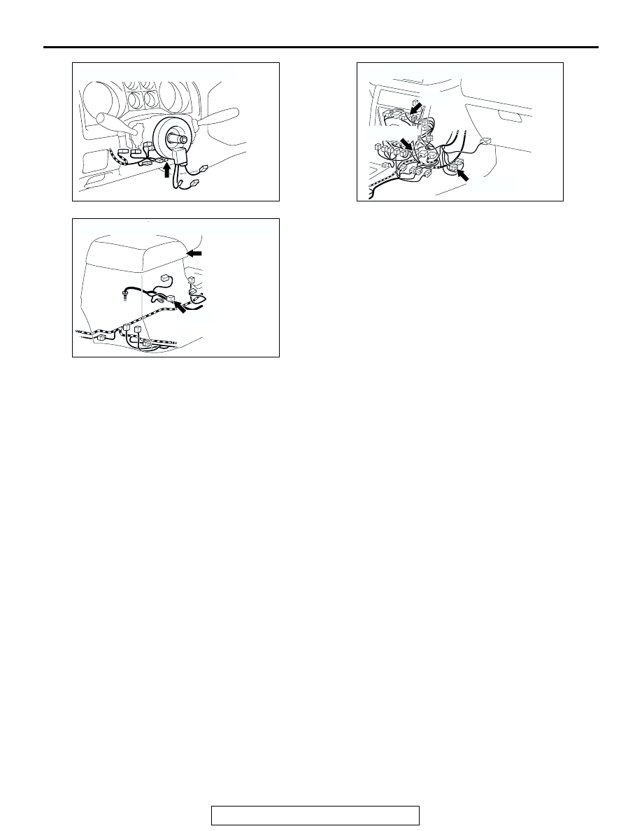
CONNECTOR: D-225
AH
AC204176
CONNECTORS: E-121, E-122, E-123
AQ
E-123(GR)
E-122(L)
E-121
AC204175
CONNECTOR: E-126
AD
E-126(GR)
FLOOR
CONSOLE