Mitsubishi Montero (2004+). Manual - part 109


  Index      Mitsubishi     Mitsubishi Montero - service repair manual 2004 year


Search            


Content   ..  107  108  109  110   ..


Mitsubishi Montero (2004+). Manual - part 109


TIMING BELT

TSB Revision

ENGINE MECHANICAL

11A-41

7. Remove the setting pin that has been inserted into the 

auto-tensioner.

8. Turn the crankshaft two turns clockwise to align the timing 

marks.

9. Wait for at least five minutes, and then check that the 

auto-tensioner pushrod extends within the standard value.

Standard value (A): 4.8 

 5.5 mm (0.19  0.22 inch)

10.If no, repeat the operation in steps (5) to (9) above.
11.Check again that the timing marks of each sprocket are 

aligned.

.

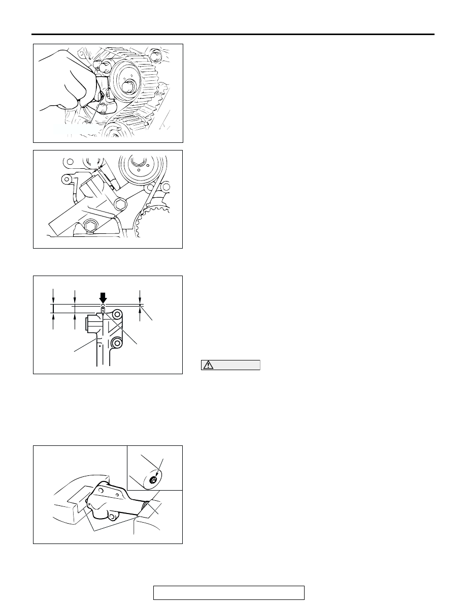
>>B<< AUTO-TENSIONER INSTALLATION
1. While holding the auto-tensioner by hand, press the end of 

the pushrod against a metal surface (such as the cylinder 
block) with a force of 98 

− 196 N (72 − 145 pound) and 

measure how far the pushrod is pushed in.

Standard value: Within 1 mm (0.04 inch)
A: Length when no force is applied
B: Length when force is applied

 B: Amount pushed in

CAUTION

• Place the auto-tensioner perpendicular to the jaws of 

the vice.

• If there is a plug at the base of the auto-tensioner, insert 

a plain washer onto the end of the auto-tensioner to 
protect the plug.

2. If it is not within the standard value, replace the 

auto-tensioner.

3. Place two dolly blocks in a vice as shown in the illustration, 

and then place the auto-tensioner in the vice.

ACX00339 AB

SETTING PIN

ACX00339

A

AB

ACX00306AB

A

B

AUTO-TENSIONER

AMOUNT 
PUSHED IN

PUSHROD

ACX00333

PLUG

PLAIN 

WASHER

DOLLY BLOCKS

AB

TIMING BELT

TSB Revision

ENGINE MECHANICAL

11A-42

CAUTION

Never compress the pushrod too fast, or the pushrod may 
be damaged.
4. Slowly compress the pushrod of the auto-tensioner until pin 

hole A in the pushrod is aligned with pin hole B in the 
cylinder.

5. Insert the setting pin into the pin holes once they are 

aligned.
NOTE: If replacing the auto-tensioner, the pin will already be 
inserted into the pin holes of the new part.

CAUTION

Do not remove the setting pin from the auto-tensioner.
6. Install the auto-tensioner to the engine.

.

>>C<< CRANKSHAFT PULLEY INSTALLATION
Use special tools MB991800 and MB991802 to install the 
crankshaft pulley.

.

>>D<< ACCESSORY MOUNT ASSEMBLY INSTALLATION
Install the bolts to the shown positions, and tighten them to the 
specified torque. 

.

>>E<< DRIVE BELT AUTO TENSIONER INSTALLATION
1. Install the drive belt auto tensioner with the Allen wrench 

inserted. 

ACX00334 AB

PIN HOLE A

PIN HOLE B

ACX01675AB

MB991800

MB991802

Bolt (symbol)

Diameter 

× length 

mm (in)

Tightening 
torque N

m (ft-lb)

A

10 

× 100 (0.4 × 3.9) 41 ± 8 (30 ± 6)

B

10 

× 30 (0.4 × 1.2)

41 

± 8 (30 ± 6)

C

10 

× 100 (0.4 × 3.9) 44 ± 10 (33 ± 7)

D

12 

× 100 (0.5 × 3.9) 74 ± 9 (54 ± 7)

E

× 30 (0.3 × 1.2)

23 

± 3 (17 ± 2)

F

10 

× 100 (0.4 × 3.9) 49 ± 5 (36 ± 4)

ACX00757AB

A

E

D

C

B

B

F

A

A

TIMING BELT

TSB Revision

ENGINE MECHANICAL

11A-43

2. After the drive belt has been installed, remove the Allen 

wrench while holding the drive belt auto tensioner with a 
socket wrench drive. Then release the drive belt auto 
tensioner slowly. 

INSPECTION

M1112004400255

AUTO-TENSIONER

• Check the auto-tensioner for possible leaks.

• Check the pushrod for cracks.

ACX01376AB

ALLEN WRENCH

ACX00536

AUTO-TENSIONER

SPRING

PUSHROD

AB

SPECIFICATIONS

TSB Revision

ENGINE MECHANICAL

11A-44

SPECIFICATIONS

FASTENER TIGHTENING SPECIFICATIONS

M1111003800417

ITEMS

SPECIFICATIONS

Accessory mount assembly mounting bolt (10 

× 100, 10 × 30)

41 

± 8 N⋅m (30 ± 6 ft-lb)

Accessory mount assembly mounting bolt (10 

× 100)

44 

± 10 N⋅m (33 ± 7 ft-lb)

Accessory mount assembly mounting bolt (12 

× 100)

74 

± 9 N⋅m (54 ± 7 ft-lb)

Accessory mount assembly mounting bolt (8 

× 30)

23 

± 3 N⋅m (17 ± 2 ft-lb)

Accessory mount assembly mounting bolt (10 

× 100)

49 

± 5 N⋅m (36 ± 4 ft-lb)

Accessory mount stay mounting bolt 

49 

± 9 N⋅m (36 ± 7 ft-lb)

Accessory mount stay mounting bolt 

24 

± 4 N⋅m (18 ± 3 ft-lb)

Auto tensioner mounting bolt 

23 

± 3 N⋅m (17 ± 2 ft-lb)

Cooling fan attaching nut

11 

± 1 N⋅m (98 ± 8 in-lb)

Cooling fan bracket assembly

41 

± 8 N⋅m (30 ± 6 ft-lb)

Camshaft position sensor support attaching bolt

14 

± 1 N⋅m (120 ± 13 in-lb)

Camshaft sprocket attaching bolt

88 

± 10 N⋅m (65 ± 7 ft-lb)

Crankshaft position sensor attaching bolt

8.5 

± 0.5 N⋅m (76 ± 4 in-lb)

Crankshaft pulley attaching bolt

185 

± 5 N⋅m (137 ± 3 ft-lb)

Cylinder head bolt <cold engine>

108 

± 5 N⋅m (80 ± 3 ft-lb)→ 0 N⋅m (0 

in-lb) 

→108 ± 5 N⋅m (80 ± 3 ft-lb)

Drive belt auto tensioner attaching bolt

24 

± 4 N⋅m (18 ± 3 ft-lb)

Drive plate attaching bolt

75 

± 1 N⋅m (55 ± 1 ft-lb)

Drain plug

39 

± 5 N⋅m (29 ± 3 ft-lb)

Drive shaft (RH) attaching nut

60 

± 10 Nm (45 ± 7 ft-lb)

Engine oil dipstick assembly attaching bolt

14 

± 1 N⋅m (120 ± 13 in-lb)

Engine front mount insulator attaching bolt

44 

± 9 N⋅m (33 ± 6 ft-lb)

Engine mount insulator attaching nut

26 

± 4 N⋅m (19 ± 3 ft-lb)

Front differential number 2 crossmember assembly attaching bolt

69 

± 9 N⋅m (51 ± 7 ft-lb)

Front propeller shaft connection nut

60 

± 10 N⋅m (45 ± 7 ft-lb)

Fuel high-pressure hose bolt

5.0 

± 1.0 N⋅m (44 ± 9 in-lb)

Ground cable mounting bolt

9.0 

± 2.0 N⋅m (80 ± 17 in-lb)

Idler pulley attaching bolt

44 

± 5 N⋅m (33 ± 3 ft-lb)

Ignition coil bolt

13 

± 2 N⋅m (111 ± 22 in-lb)

Intake manifold plenum stay bolt

39 

± 3 N⋅m (29 ± 2 ft-lb)

Oil cooler eye bolt

48 

± 7 N⋅m (36 ± 5 ft-lb)

Oil cooler hose bracket bolt

12 

± 2 N⋅m (102 ± 22 in-lb)

Oil pan attaching bolt

8.5 

± 3.5 N⋅m (75 ± 31 in-lb)

Oil pan attaching bolt

37 

± 7 N⋅m (27 ± 5 ft-lb)

Oil pan attaching bolt

11 

± 0.5 N⋅m (93 ± 4 ft-lb)

Oil screen attaching bolt

19 

± 3 N⋅m (14 ± 2 ft-lb)

Oil screen attaching bolt

9.0 

± 1.0 N⋅m (80 ± 9 in-lb)

Power steering oil pump assembly mounting bolt

22 

± 4 N⋅m (16 ± 3 ft-lb)


Content   ..  107  108  109  110   ..