Mitsubishi Montero (2004+). Manual - part 1034


  Index      Mitsubishi     Mitsubishi Montero - service repair manual 2004 year


Search            


Content   ..  1032  1033  1034  1035   ..


Mitsubishi Montero (2004+). Manual - part 1034


ON-VEHICLE SERVICE

TSB Revision

BASIC BRAKE SYSTEM

35A-135

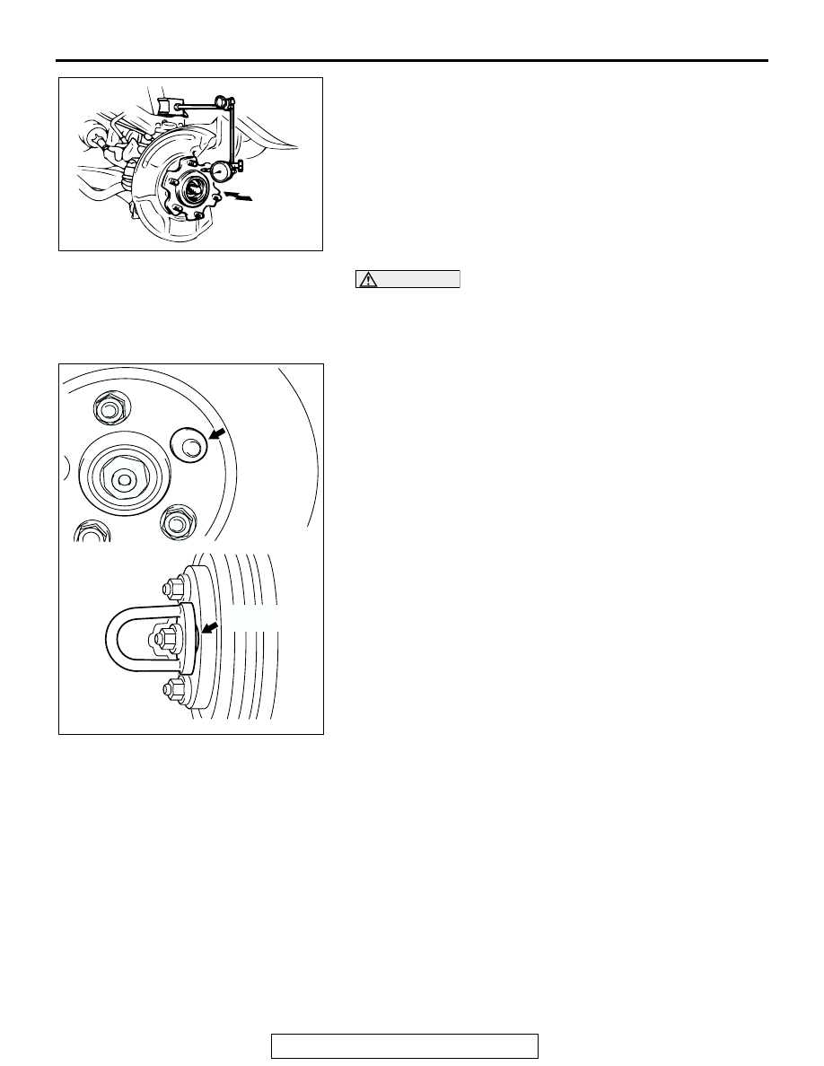
(2) Remove the brake disc. Then place a dial gauge as 

shown in the illustration, and then move the hub in the 
axial direction and measure the play.

Limit: 0 mm (0 inch)

(3) If the play exceeds the limit, disassemble the hub and 

knuckle assembly to check each part.

(4) If the play does not exceed the limit, install the brake disc 

at a different phase, and then check the run-out of the 
brake disc again.

CAUTION

• After a new brake disc is installed, always grind the 

brake disc with a on-car type brake lathe. If this step is 
not carried out, the brake disc run-out will exceed the 
specified value, resulting in judder.

• When the on-car type lathe is used, first install a M12 

flat washer on the stud bolt in the brake disc side 
according to the figure, and then install the adapter. If 
the adapter is installed without a M12 flat washer, the 
brake disc rotor may be deformed, resulting in inaccu-
rate grinding.

• Grind the brake disc with all wheel nuts diagonally and 

equally tightened to the specified torque 100 N

m (74 

ft-lb). When all numbers of wheel nuts are not used, or 
the tightening torque is excessive or not equal, the 
brake disc rotor or drum may be deformed, resulting in 
judder.

6. If the run-out cannot be corrected by changing the phase of 

the brake disc, replace the brake disc or turn rotor with an 
on-car type brake lathe ("Accuturn-8750" or equivalent).

ACX00670

AC005154 AB

M12 PLANE 
WASHER

M12 PLANE 
WASHER

BRAKE PEDAL

TSB Revision

BASIC BRAKE SYSTEM

35A-136

BRAKE PEDAL

REMOVAL AND INSTALLATION

M1351003400257

INSTALLATION SERVICE POINT

.

>>A<< BRAKE PEDAL AND PEDAL SUPPORT MEMBER 
ASSEMBLY INSTALLATION
Tighten the brake booster mounting nut ("A" in the illustration) 
first, then tighten the brake pedal mounting bolt ("B" in the illus-
tration).
NOTE: Because the mounting hole of the pedal mounting bolt 
("B" in the illustration) is a slotted hole, if the pedal mounting 
bolt ("B" in the illustration) is mounted first, positioning 
becomes impossible.

Post-installation Operation
• Brake Pedal Adjustment (Refer to 

P.35A-117

.)

ACX01838 AB

14 ± 3 N·m
124 ± 26 in-lb

12 ± 2 N·m
107 ± 17 in-lb

1

2

N

N

3

4

5

6

7

8

9

10

11

12

REMOVAL STEPS

INSTRUMENT PANEL LOWER 
PANEL (REFER TO GROUP 52A, 
INSTRUMENT PANEL 

P.52A-3

.)

1.

RETURN SPRING

2.

COTTER PIN

3.

SHIFT LOCK CABLE 
CONNECTION

4.

HARNESS CONNECTOR

5.

STOPLIGHT SWITCH

6.

ADJUSTER

7.

PEDAL STOPPER

8.

SNAP PIN

9.

CLEVIS PIN

10.

PEDAL PAD

11.

BRAKE BOOSTER MOUNTING 
NUT

>>A<<

12.

BRAKE PEDAL AND PEDAL 
SUPPORT MEMBER ASSEMBLY

REMOVAL STEPS (Continued)

ACX01839 AB

A

A

B

HYDRAULIC BRAKE BOOSTER (HBB)

TSB Revision

BASIC BRAKE SYSTEM

35A-137

HYDRAULIC BRAKE BOOSTER (HBB)

REMOVAL AND INSTALLATION

M1351010700056

CAUTION

To prevent damaging the HBB pump motor, do not turn the ignition switch to the "ON" position until 
installation is completed and brake fluid is replenished.

Pre-removal Operation
• Bleeding of the brake fluid power supply system (Depress 

the brake pedal repeatedly more than 40 times with the 

ignition switch at the LOCK (OFF) position.)

• Brake Fluid Draining

Post-installation Operation
• Brake Pedal Adjustment (Refer to 

P.35A-117

.)

• Brake Fluid Supplying

• Brake Line Bleeding (Refer to 

P.35A-125

.)

• HBB Operating Check (Refer to 

P.35A-120

.)

ACX00672 AB

2

2

6

4

3

7

7

8

5

1

14 ± 3 N

·

m

124 ± 26 in-lb

15 ± 2 N

·

m

11 ± 2 ft-lb

N

N

REMOVAL STEPS

BATTERY

1.

HARNESS CONNECTORS

2.

BRAKE TUBE CONNECTION

3.

SNAP PIN

4.

CLEVIS PIN

5.

HBB MOUNTING NUT

<<A>> >>A<<

6.

HBB

7.

SEAL

8.

SPACER

REMOVAL STEPS (Continued)

HYDRAULIC BRAKE BOOSTER (HBB)

TSB Revision

BASIC BRAKE SYSTEM

35A-138

REMOVAL SEVICE POINT

.

<<A>> HBB REMOVAL

CAUTION

Since high-pressure is applied to the tube shown in the 
illustration, do not bend it.

INSTALLATION SEVICE POINT

.

>>A<< HBB INSTALLATION

CAUTION

Since high-pressure is applied to the tube shown in the 
illustration, do not bend it.

ACCUMULATOR REPLACEMENT

M1351015800014

Required Special Tool:

• MB991926: Accumulator Wrench

1. Depress the brake pedal repeatedly more than 40 times until 

the pedal depressing force feels heavy with the ignition 
switch at the "LOCK" (OFF) position to release the pressure 
of the HBB power supply system.

CAUTION

To prevent damaging the pump motor, do not turn the igni-
tion switch to the "ON" position until brake fluid is replen-
ished.
2. Drain the brake fluid.

AC204332

AC204332


Content   ..  1032  1033  1034  1035   ..