Mitsubishi Montero (2004+). Manual - part 1024


  Index      Mitsubishi     Mitsubishi Montero - service repair manual 2004 year


Search            


Content   ..  1022  1023  1024  1025   ..


Mitsubishi Montero (2004+). Manual - part 1024


HYDRAULIC BRAKE BOOSTER (HBB) DIAGNOSIS

TSB Revision

BASIC BRAKE SYSTEM

35A-95

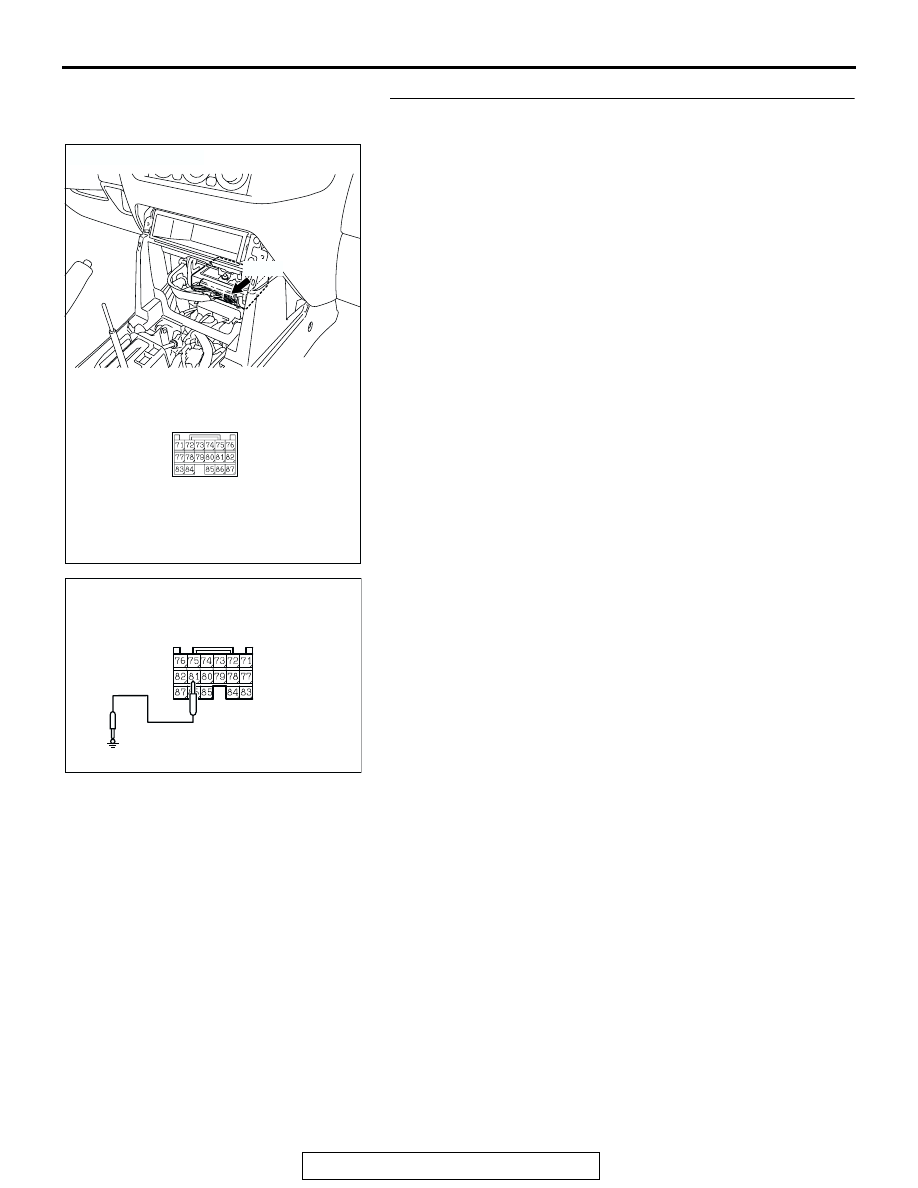
STEP 2. Check the brake warning light drive circuit at 
M-ASTC-ECU harness connector E-121.

(1) Disconnect M-ASTC-ECU connector E-121 and check at 

the harness connector (component side).

(2) Turn the ignition switch to the "ON" position.

(3) Connect terminal 81 to a body ground.
Q: Does the brake warning light turn off?

YES : Replace the M-ASTC-ECU (Refer to GROUP 35C, 

M-ASTC-ECU 

P.35C-213

). Then go to Step 4.

NO :  Go to Step 3.

AC203901

AC204627AP

CONNECTOR: E-121

M-ASTC-ECU CONNECTOR

E-121

E-121

AC204691AB

E-121

HARNESS CONNECTOR: 
COMPONENT SIDE

HYDRAULIC BRAKE BOOSTER (HBB) DIAGNOSIS

TSB Revision

BASIC BRAKE SYSTEM

35A-96

STEP 3. Check the following harness wire.

• The wire between combination meter connector D-03 (ter-

minal 55) and M-ASTC-ECU connector E-121 (terminal 81)

NOTE:  Also check intermediate connector E-111 for loose, cor-
roded, or damaged terminals, or terminals pushed back in the 
connector. If intermediate connector E-111 is damaged, repair 
or replace the damaged component(s) as described in GROUP 
00E, Harness Connector Inspection 

P.00E-2

. If the connector 

has been repaired or replaced, go to Step 4.

Q: Is the harness wire damaged?

YES : Repair or replace it and then go to Step 4.
NO :  Replace the combination meter (Refer to GROUP 

54A, Combination Meter and Vehicle Speed Sensor 

P.54A-76

) and then go to Step 4.

AC204690 AC

CONNECTOR: D-03

D-03 (GR)

HARNESS CONNECTOR: 
COMPONENT SIDE

D-03

AC203901

AC204627AR

CONNECTOR: E-121

E-121

E-121

HARNESS CONNECTOR: 
COMPONENT SIDE

AC204548AK

CONNECTOR: E-111

E-111

HYDRAULIC BRAKE BOOSTER (HBB) DIAGNOSIS

TSB Revision

BASIC BRAKE SYSTEM

35A-97

STEP 4. Retest the system.
Q: Does the brake warning light turn on for three seconds 

and then turn off on start-up?
YES : 
The procedure is complete.
NO :  Start over at Step 1.

INSPECTION PROCEDURE 3: DTC 53 <Seizure of the Pump Motor>, DTC55 or DTC57 is set, but the 
Buzzer does not Sound.

AC204502AB

Buzzer Circuit

HYDRAULIC BRAKE BOOSTER (HBB) DIAGNOSIS

TSB Revision

BASIC BRAKE SYSTEM

35A-98

.

CIRCUIT OPERATION

• The M-ASTC-ECU controls the buzzer by turning 

the power transistor in the M-ASTC-ECU ON and 
OFF.

• The M-ASTC-ECU outputs the buzzer-sounding 

signal at the malfunction of the hydraulic brake 
booster (HBB). (Also the M-ASTC-ECU turns on 
the brake warning light at the same time.)

• The buzzer will sound under the following cases:

a. When the pump motor is locked (DTC 53 is 

set).

b. When the pump motor is energized abnor-

mally for long period (DTC 55 is set).

c. When the accumulator pressure is abnormally 

low (DTC 57 is set).

d. When the solenoid valve temperature in the 

M-ASTC-ECU is abnormally high (DTC is not 
set). 

.

TECHNICAL DESCRIPTION (COMMENT)
The cause is probably an open circuit at the buzzer 
circuit, a malfunction of the buzzer or a failure of 
buzzer drive transistor in the M-ASTC-ECU.

.

TROUBLESHOOTING HINTS

• Damaged wiring harness or connector

• Malfunction of the buzzer

• Malfunction of the M-ASTC-ECU

.

DIAGNOSIS

Required Special Tool:

• MB991223: Harness Set

AC204688 AB

CONNECTOR: D-116

D-116

AC204547AB

CONNECTORS: D-208, D-212

D-208

D-212

JUNCTION BLOCK
(FRONT VIEW)

AC204548AH

CONNECTORS: E-107, E-111

E-111

E-107

AC203901AF

CONNECTOR: E-120

E-120


Content   ..  1022  1023  1024  1025   ..