Mitsubishi Montero (2004+). Manual - part 1015


  Index      Mitsubishi     Mitsubishi Montero - service repair manual 2004 year


Search            


Content   ..  1013  1014  1015  1016   ..


Mitsubishi Montero (2004+). Manual - part 1015


HYDRAULIC BRAKE BOOSTER (HBB) DIAGNOSIS

TSB Revision

BASIC BRAKE SYSTEM

35A-59

.

CIRCUIT OPERATION

• The pump motor operates if the motor relay A or 

motor relay B turn to ON. 

• The M-ASTC-ECU monitors the pump motor (at 

25 terminal). 

.

HBB DTC SET CONDITIONS
DTC 55 will be set when the pump motor has been 
energized too long. The M-ASTC-ECU sounds the 
buzzer continuously to inform the trouble of the driver 
and protects the pump motor by activating the pump 
motor intermittently.

.

TROUBLESHOOTING HINTS

• Malfunction of the motor relay A or the motor 

relay B

• Malfunction of the pressure switch (for pump 

motor control) [Integrated with the hydraulic 
brake booster (HBB)]

• Damaged wiring harness or connector

• Malfunction of the M-ASTC-ECU

.

DIAGNOSIS

Required Special Tool:

•  MB991958: Scan Tool (MUT-III Sub Assembly)

• MB991824: Vehicle Communication Interface (V.C.I.)

• MB991827: MUT-III USB Cable

• MB991911: MUT-III Main Harness B
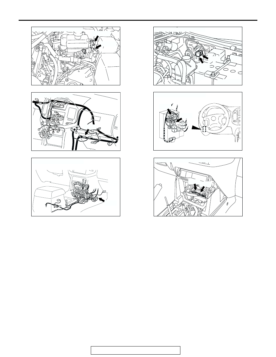
AC204545 AC

CONNECTORS: B-17, B-18

B-17 (GR)

B-18 (B)

AC204329 AC

CONNECTORS: B-53X, B-54X

B-53X

B-54X

AC204688 AB

CONNECTOR: D-116

D-116

AC204547AB

CONNECTORS: D-208, D-212

D-208

D-212

JUNCTION BLOCK
(FRONT VIEW)

AC204548 AB

CONNECTOR: E-111

E-111

AC203901AD

CONNECTORS: E-119, E-120

E-119

E-120

HYDRAULIC BRAKE BOOSTER (HBB) DIAGNOSIS

TSB Revision

BASIC BRAKE SYSTEM

35A-60

• MB991223: Harness Set

STEP 1. Check the pump motor operation.

Remove the motor relay A.
Q: Does the pump motor stop?

YES : Remove the motor relay A. Then go to Step 15.
NO :  Go to Step 2.

STEP 2. Check the pump motor operation.

Remove the motor relay B.
Q: Does the pump motor stop?

YES : Remove the motor relay B. Then go to Step 15.
NO :  Go to Step 3.

AC204329 AD

MOTOR 
RELAY A

AC204329 AE

MOTOR 
RELAY B

HYDRAULIC BRAKE BOOSTER (HBB) DIAGNOSIS

TSB Revision

BASIC BRAKE SYSTEM

35A-61

STEP 3. Check the power supply circuit at HBB harness 
connector B-18.

(1) Disconnect HBB connector B-18.

(2) Measure the voltage between terminal 31 and ground. The 

voltage should measure 0 volt.

Q: Is the measured voltage 0 volt?

YES : Go to Step 5.
NO :  Go to Step 4.

AC204629 AD

CONNECTOR: B-18

B-18 (B)

HBB CONNECTOR

B-18

AC204632

34

32

31

33

35

AB

HARNESS CONNECTOR: 
COMPONENT SIDE

B-18 (B)

HYDRAULIC BRAKE BOOSTER (HBB) DIAGNOSIS

TSB Revision

BASIC BRAKE SYSTEM

35A-62

STEP 4. Check the following harness wire.

• The wire between motor relay A connector B-53X (terminal 

4) and HBB connector B-18 (terminal 31)

Q: Is the harness wire damaged?

YES : Repair or replace it and then go to Step 15.
NO :  Go to Step 15.

AC204551

3  2  1

5     4

1  2  3

4     5

RELAY BOX CONNECTOR

AC

CONNECTOR: B-53X

B-53X

AC204626 AB

CONNECTOR: B-18

B-18 (B)

HARNESS CONNECTOR : 
COMPONENT SIDE

34

32

31

33

35

B-18


Content   ..  1013  1014  1015  1016   ..