Mitsubishi Montero (2004+). Manual - part 1013


  Index      Mitsubishi     Mitsubishi Montero - service repair manual 2004 year


Search            


Content   ..  1011  1012  1013  1014   ..


Mitsubishi Montero (2004+). Manual - part 1013


HYDRAULIC BRAKE BOOSTER (HBB) DIAGNOSIS

TSB Revision

BASIC BRAKE SYSTEM

35A-51

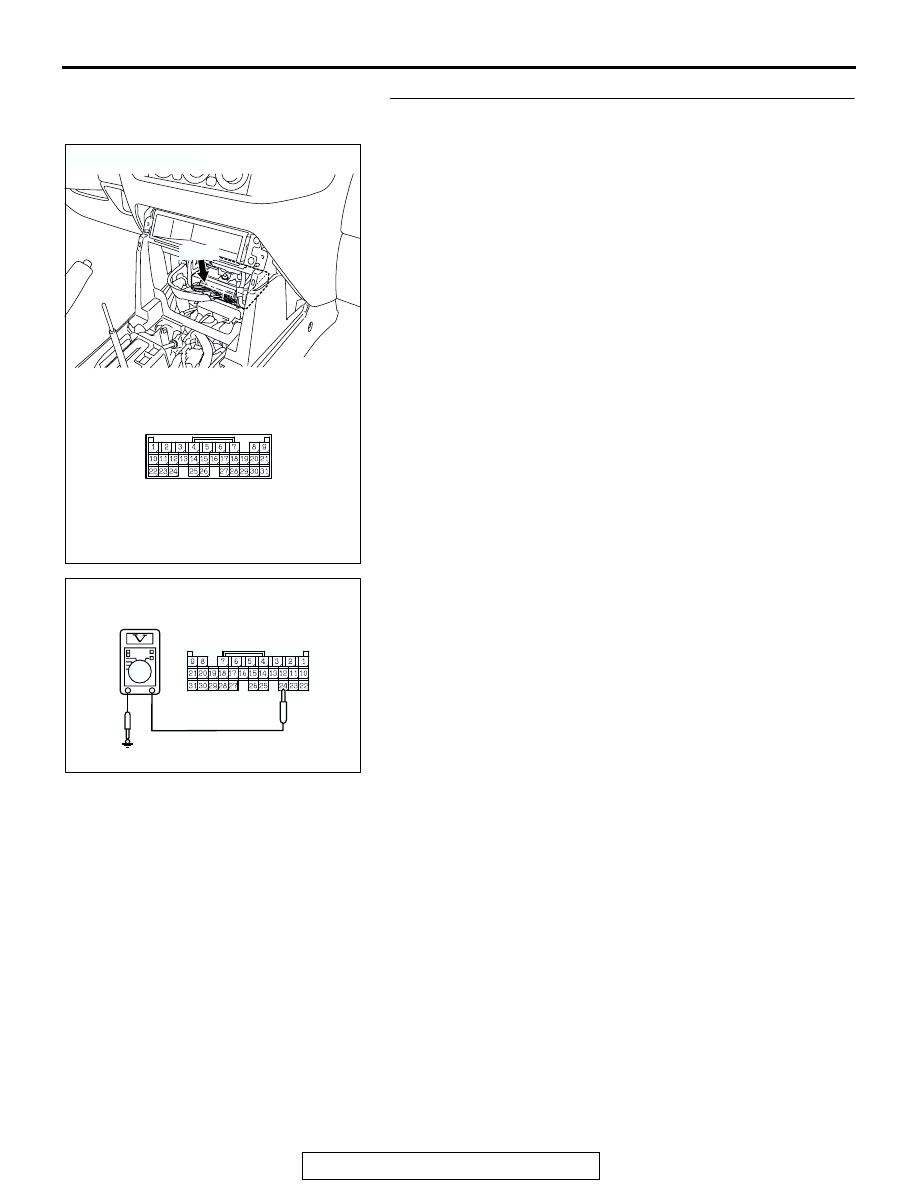
STEP 17. Check the ignition switch (IG2) circuit at 
M-ASTC-ECU harness connector E-119.

(1) Disconnect M-ASTC-ECU connector E-119.
(2) Turn the ignition switch to the "ON" position.

(3) Measure the voltage between terminal 24 and ground. The 

voltage should measure approximately 12 volts (battery 
positive voltage).

Q: Is battery positive voltage (approximately 12 volts) 

present?
YES : 
Go to Step 20.
NO :  Go to Step 19.

AC203901

AC204627 AB

CONNECTOR: E-119

E-119

M-ASTC-ECU CONNECTOR

E-119

AC204631AB

HARNESS CONNECTOR: 
COMPONENT SIDE

E-119

HYDRAULIC BRAKE BOOSTER (HBB) DIAGNOSIS

TSB Revision

BASIC BRAKE SYSTEM

35A-52

STEP 18. Check the following harness wire.

• The wire between M-ASTC-ECU connector E-120 (terminal 

48) and motor relay A connector B-53X (terminal 1)

Q: Is the harness wire damaged?

YES : Repair or replace it and then go to Step 25.
NO :  Go to Step 25.

AC203901

AC204627AG

CONNECTOR: E-120

E-120

HARNESS CONNECTOR: 
COMPONENT SIDE

E-120

AC204551

3  2  1

5     4

1  2  3

4     5

RELAY BOX CONNECTOR

AC

CONNECTOR: B-53X

B-53X

HYDRAULIC BRAKE BOOSTER (HBB) DIAGNOSIS

TSB Revision

BASIC BRAKE SYSTEM

35A-53

STEP 19. Check the following harness wire.

• The wire between M-ASTC-ECU connector E-119 (terminal 

24) and motor relay B connector B-54X (terminal 1)

Q: Is the harness wire damaged?

YES : Repair or replace it and then go to Step 25.
NO :  Go to Step 25.

AC203901

AC204627AC

CONNECTOR: E-119

E-119

HARNESS CONNECTOR: 
COMPONENT SIDE

E-119

AC204551

3  2  1

5     4

1  2  3

4     5

RELAY BOX CONNECTOR

AD

CONNECTOR: B-54X

B-54X

HYDRAULIC BRAKE BOOSTER (HBB) DIAGNOSIS

TSB Revision

BASIC BRAKE SYSTEM

35A-54

STEP 20. Check the HBB (continuity and resistance test of 
the pump motor).

(1) Disconnect HBB connectors B-17 and B-18.

(2) Check for continuity and measure the resistance between 

terminals at the HBB connectors.

Q: Does continuity exist between above terminals?

YES : Go to Step 22.
NO :  Go to Step 21.

STEP 21. Check the pump motor and lead wire.

(1) Remove the HBB (Refer to 

P.35A-137

).

(2) Remove the pump motor and the lead wire from the HBB 

(Refer to 

P.35A-140

).

(3) Check the following items:

• Confirm that the pump motor operates when the battery 

voltage is imposed at the pump motor terminal.

• Confirm the continuity of the lead wire.

Q: Are both of the pump motor and the lead wire in good 

condition?
YES : 
Replace the master cylinder and hydraulic unit 

assembly (Refer to 

P.35A-140

). Then go to Step 25.

NO :  Replace the pump motor or the lead wire (Refer to 

P.35A-140

). Then go to Step 25.

TESTER 
CONNECTION

SPECIFIED 
CONDITION

RESISTANCE 


(REFERENCE VALUE)

− 7

Continuity

10 or less

− 31

Continuity

Less than 2

− 32

Continuity

Approximately 33

− 32

Continuity

Less than 2

31 

− 32

Continuity

10 or less

AC204629 AB

CONNECTORS: B-17, B-18

B-17 (GR)

B-18 (B)

B-17

B-18

HBB CONNECTORS

ACX00662AC

B-18

B-17


Content   ..  1011  1012  1013  1014   ..