Mitsubishi Montero (2004+). Manual - part 36


  Index      Mitsubishi     Mitsubishi Montero - service repair manual 2004 year


Search            


Content   ..  34  35  36  37   ..


Mitsubishi Montero (2004+). Manual - part 36


CENTRALIZED JUNCTION

TSB Revision

CIRCUIT DIAGRAMS

90-23

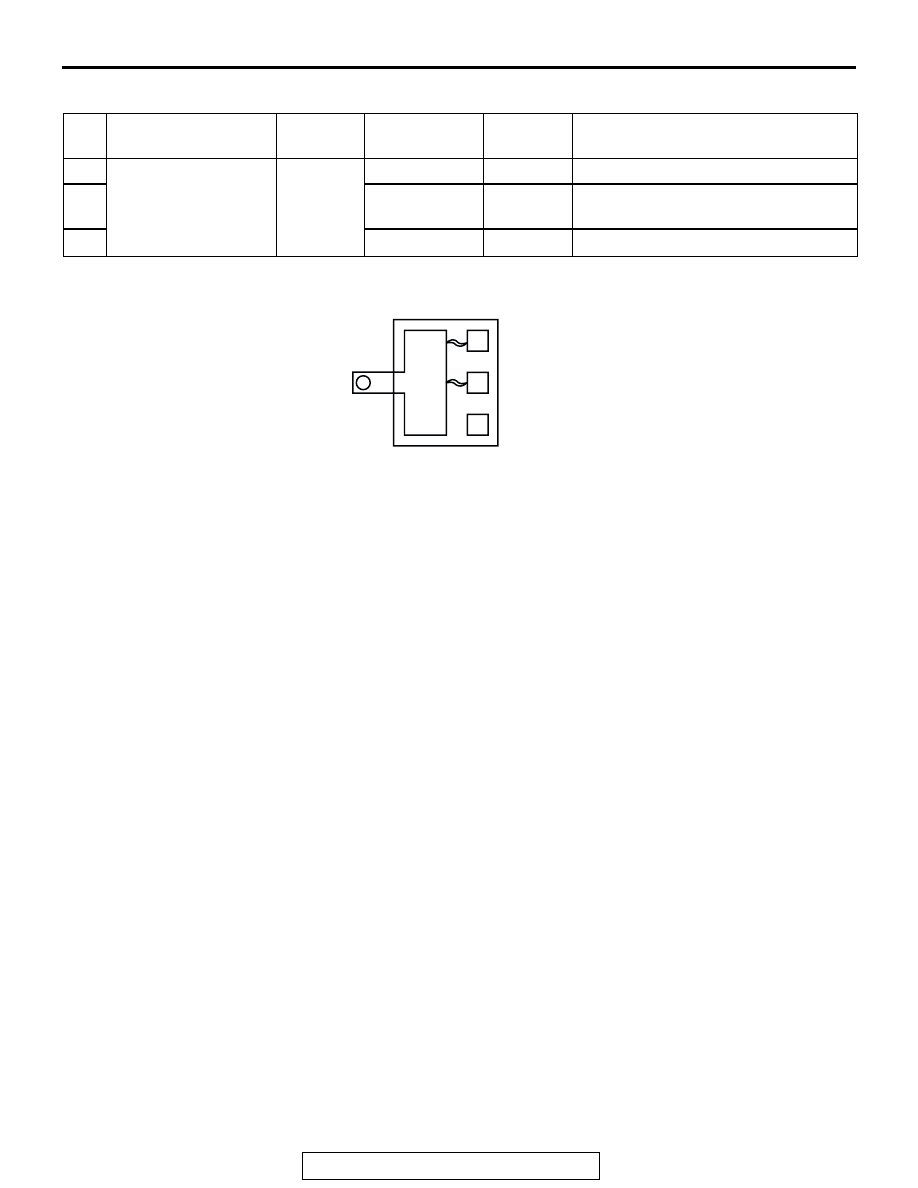
ENGINE COMPARTMENT (CONNECTED DIRECTLY TO BATTERY POSITIVE TERMINAL)

NO. POWER SUPPLY 

CIRCUIT

NAME

RATED 
CAPACITY (A)

HOUSING 
COLOR

LOAD CIRCUIT

31

Battery

Fusible 
link

60

Yellow

Valve relay

32

40

Green

Hydraulic brake booster (HBB) and 
motor relay A, B

33

ACX01517

(CONNECTED DIRECTLY TO BATTERY POSITIVE TERMINAL)

31

32

33

AC

CENTRALIZED JUNCTION

TSB Revision

CIRCUIT DIAGRAMS

90-24

PASSENGER COMPARTMENT

NO. POWER SUPPLY 

CIRCUIT

NAME

RATED 
CAPACITY (A)

HOUSING 
COLOR

LOAD CIRCUIT

1

Ignition switch (ACC) Fuse

15

Blue

ETACS-ECU, rear wiper motor, 
remote controlled mirror and remote 
controlled mirror switch

2

3

4

15

Blue

Cigarette lighter and RV meter

5

Ignition switch (IG2)

10

Red

A/C compressor clutch relay, 
A/C-ECU, A/C switch, automatic 
compressor controller, condenser fan 
control relay, defogger relay, front 
blower relay, front-ECU, heated seat 
relay, M-ASTC-ECU, motor relay A, 
outside/inside air selection damper 
control motor, rear A/C control unit, 
rear A/C switch, rear A/C unit, rear 
blower relay, rear cooler control unit, 
rear cooler switch, rear cooler unit, 
rear fan control switch (front), rear 
heater control unit, rear heater switch, 
steering wheel sensor, sunroof motor 
assembly, tone alarm, transfer-ECU 
and valve relay

6

Ignition switch (IG1)

10

Red

Column switch, combination meter, 
ETACS-ECU, motor antenna-ECU, 
side step light-ECU, solenoid valve A, 
B, SRS-ECU, TMPS receiver and 
vehicle speed sensor

7

8

10

Red

Combination meter, ETACS-ECU, 
front propeller shaft speed sensor, 
G/yaw rate sensor, input shaft speed 
sensor, output shaft speed sensor, 
powertrain control module, rear 
combination light, rear propeller shaft 
speed sensor, shift switch assembly, 
SRS-ECU, transfer-ECU, transfer 
shift lever switch and transmission 
range switch

CENTRALIZED JUNCTION

TSB Revision

CIRCUIT DIAGRAMS

90-25

9

Fusible link No.2

Fuse

10

20

Yellow

Combination meter, data link 
connector and ETACS-ECU

11

30

Pink

Defogger, defogger relay and fuse 
No.18 (in junction block) circuit

12

30

Pink

Automatic compressor controller, 
blower motor, blower resistor, blower 
switch, front blower relay and heater 
blower controller unit

13

14

15

16

17

Ignition switch (IG2)

10

Red

 M-ASTC-ECU and motor relay B

18

Defogger relay

10

Red

Remote controlled mirror

19

Fusible link No.4

20

Yellow

Sunroof motor assembly

20

Fusible link No.3

20

Yellow

Heated seat relay and heated seat 
switch

NO. POWER SUPPLY 

CIRCUIT

NAME

RATED 
CAPACITY (A)

HOUSING 
COLOR

LOAD CIRCUIT

AC203972

17

18

19

20

(IN JUNCTION BLOCK)

AB

1

2

3

4

5

6

7

8

11

13

14

15

9

16

12

10

CENTRALIZED JUNCTION

TSB Revision

CIRCUIT DIAGRAMS

90-26

CENTRALIZED RELAY

CONNECTOR NO.

NAME

CONNECTOR NO.

NAME

A-06X

B-20X

A-07X

Front-ECU

B-21X

Valve relay

A-08X

Front-ECU

B-22X

MFI relay

A-09X

Condenser fan control relay

B-23X

Throttle actuator control 
motor relay

A-10X

Horn relay

A-11X

Theft-alarm horn relay

B-24X

Fuel pump relay (2)

A-12X

A/C compressor clutch relay

B-25X

Inspection connector (engine 
speed detection connector)

A-13X

Fog light relay

B-53X

Motor relay A

B-19X

Fuel pump relay (1)

B-54X

Motor relay B

AC303851AC

(RELAY BOX IN ENGINE COMPARTMENT)

FRONT OF 
VEHICLE

A-06X

A-07X

A-08X

A-10X

A-11X

A-12X

A-13X

2

10

11

21

22

23

24

25

26

27

28

29

30

31

1

3

4

5

1

2

3

4

5

6

7

8

9

2
1

3

4

5

2
1

3

4

5

2
1

3

4

5

A-09X

2
1

3

4

5


Content   ..  34  35  36  37   ..