Index Mitsubishi Mitsubishi Montero - service repair manual 2004 year
Search
Content .. 33 34 35 36 ..
Mitsubishi Montero (2004+). Manual - part 35
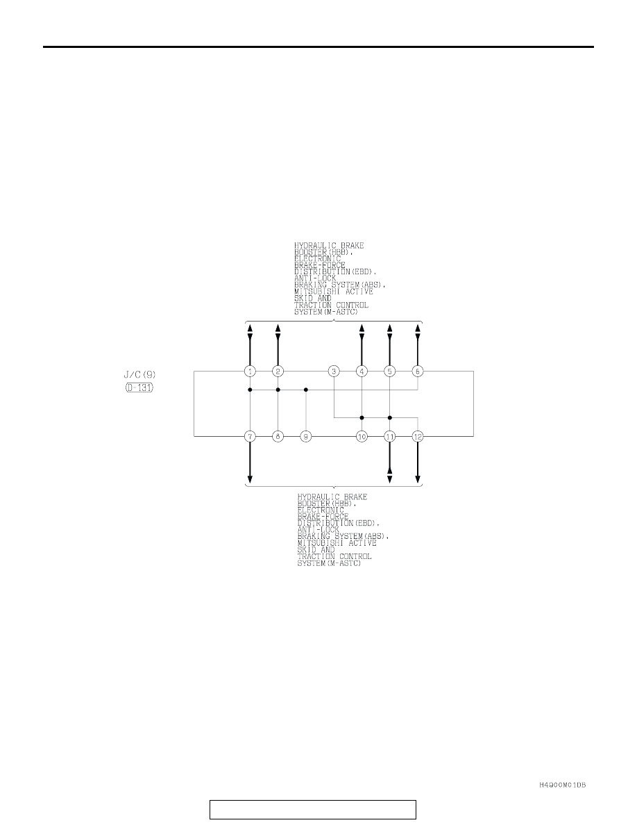
JOINT CONNECTOR
TSB Revision
CIRCUIT DIAGRAMS
90-19