Mitsubishi Montero (2004+). Manual - part 14


  Index      Mitsubishi     Mitsubishi Montero - service repair manual 2004 year


Search            


Content   ..  12  13  14  15   ..


Mitsubishi Montero (2004+). Manual - part 14


MAINTENANCE SERVICE

TSB Revision

GENERAL <BODY AND CHASSIS>

00-49

19. DRIVE SHAFT BOOTS (INSPECT FOR 
GREASE LEAKS AND DAMAGE)

M1001003600330

1. These components, which are permanently lubricated at the 

factory, do not require periodic lubrication. Damaged seals 
and boots should be replaced to prevent leakage or grease 
contamination.

2. Inspect the dust cover and boots for proper sealing, leakage 

and damage. Replace them if defective.

20. SUSPENSION SYSTEM (INSPECT FOR 
LOOSENESS AND DAMAGE)

M1001009600060

Visually inspect the front/rear suspension components for dete-
rioration and damage. Re-tighten the front/rear suspension 
components retaining bolts to specified torque.

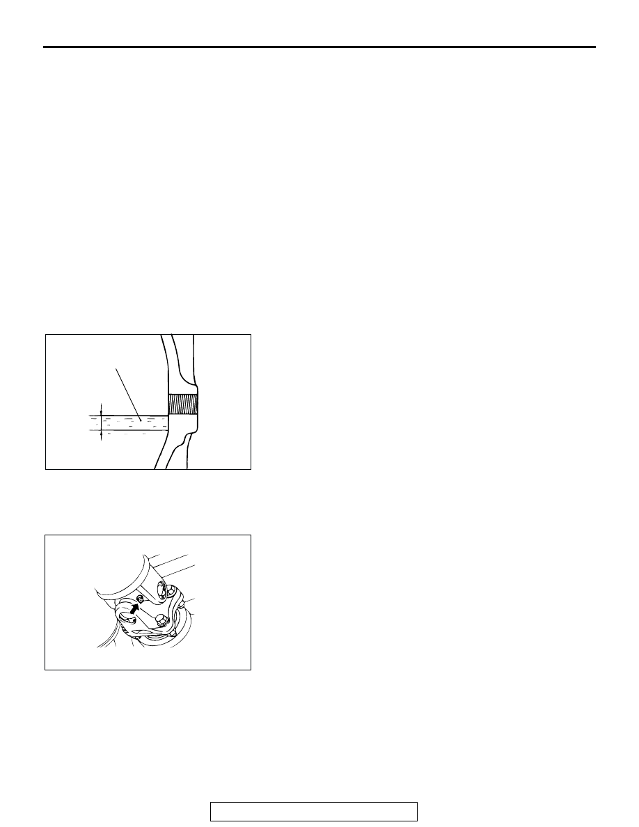
21. REAR AXLE OIL (CHECK OIL LEVEL)

M1001007500078

Rear differential Oil Check

Check that gear oil level is not 5 mm (0.2 inch) below the bot-
tom of filler plug hole.

Specified gear oil: Hypoid gear oil API classification 
GL-5 or higher

Above 

23°C(10°F): SAE90, 85W-90, 80W-90

From 

34°C to 23°C(30°F to 10°F): SAE80W, 

80W-90

Below 

34°C(30°F): SAE75W

22. PROPELLER SHAFT JOINTS WITH GREASE 
NIPPLE (LUBRICATE WITH GREASE)

M1001007300104

Lubricate the propeller shaft joints with grease.
The propeller shaft joints should be repacked with multipurpose 
grease.

ACX01083AB

GEAR OIL

UPPER
LIMIT

LOWER
LIMIT

5 mm
(0.2 in)

ACX01798

MAINTENANCE SERVICE

TSB Revision

GENERAL <BODY AND CHASSIS>

00-50

23. SRS AIR BAG (INSPECT FOR SRS SYSTEM)

M1001003700348

The SRS must be inspected by an authorized dealer 10 years 
after the car manufacture date shown on the certification label 
located on the left center sill.

.

SRS Warning Light Check

Turn the ignition key to the "ON" position. Does the "SRS" 
warning light illuminate for about seven seconds, and then 
remain off for at least five seconds after turning OFF? If yes, 
the SRS system is functioning properly. If no, refer to GROUP 
52B, Diagnosis 

P.52B-22

.

.

SRS Component Visual Check

DANGER

Wait at least 60 seconds after disconnecting the bat-
tery cable before doing any further work. The SRS 
system is designed to retain enough voltage to 
deploy the air bag for a short time even after the bat-
tery has been disconnected, so serious injury may 
result from unintended air bag deployment if work is 
done on the SRS system immediately after the battery 
cable is disconnected.

WARNING

Battery posts, terminals and related accessories con-
tain lead and lead compounds. WASH HANDS AFTER 
HANDLING.

1. Turn the ignition switch to the "LOCK" (OFF) position, 

disconnect the negative battery cable and tape the terminal.

2. Remove the floor console assembly. (Refer to GROUP 52A, 

Floor Console 

P.52A-7

.)

3. Disconnect a connector from the SRS-ECU.

.

ACX00901

2000

AB

DATE OF
MANUFACTURE

CERTIFICATION LABEL

ACX01667

AT

TEMP

SRS

P
R
N
D

5
4
3
2
1

x1000r/min

2

3

4

5

6

7

8

1

AB

SRS WARNING LIGHT

ACX00902 AB

TAPE

BATTERY

BATTERY CABLE

MAINTENANCE SERVICE

TSB Revision

GENERAL <BODY AND CHASSIS>

00-51

Front Impact Sensors
1. Check that the arrows on the sensors face toward the front 

of the vehicle.

WARNING

The SRS may not activate if a front impact sensor is 
not installed properly, which could result in serious 
injury or death to the vehicle's driver and passenger.

2. Check the radiator support panel and front impact sensor for 

deformation or rust.

3. Check the front impact sensor wiring harness for 

binding;check the connector for damage; and check the 
terminals for deformation.
Replace the sensor and/or wiring harness if they fail the 
visual check. (Refer to GROUP 52B, SRS Service 
Precautions 

P.52B-18

 and GROUP 52B, Front Impact 

Sensor 

P.52B-211

.)

.

Side Impact Sensors

WARNING

If the side impact sensor is not installed securely 
and correctly, the side-airbag may not operate nor-
mally.

If a dent, crack, deformation or rust is detected, 
replace with a new sensor.

1. Check the side impact sensor for dents, cracks or 

deformation. The side impact sensors are located inside the 
center pillars (LH/RH).

2. Check the connector for damage, and terminal for 

deformation.

3. Check that there is no bending or corrosion in the center 

pillars (LH/RH).

NOTE: The illustration at left shows the right side impact sen-
sor (RH). The position of the side impact sensor (
LH) is symmetrical to this.

.

ACX01318

FRONT IMPACT SENSORS

AB

ACX00591AC

SIDE 
IMPACT 
SENSOR

CENTER
PILLAR

FORWARD

MAINTENANCE SERVICE

TSB Revision

GENERAL <BODY AND CHASSIS>

00-52

SRS Air Bag Control Unit (SRS-ECU) 

WARNING

The SRS may not activate if the SRS-ECU (with 
built-in safing G-sensor and analog G-sensor) is not 
installed properly, which could result in serious injury 
or death to the vehicle's driver and passenger.

1. Check the SRS-ECU case and brackets for dents, cracks, 

deformation or rust.

2. Check the connector for damage, and check the terminals 

for deformation or rust.
Replace the SRS-ECU if it fails the visual check. (Refer to 
GROUP 52B, SRS Air bag Control Unit 

P.52B-215

.)

.

Air Bag Module, Steering Wheel and Clock Spring 

WARNING

The removed air bag module should be stored in a 
clean, dry place with the pad cover face up.

1. Remove the air bag module, steering wheel and clock 

spring. (Refer to GROUP 52B, Air Bag Module and Clock 
Spring 

P.52B-217

.)

2. Check the pad cover for dents, cracks or deformation.
3. Check the connector for damage and deformed terminals, 

and check the harness for binding.

4. Check the air bag inflator case for dents, cracks or 

deformation.

5. Check the harness (built into the steering wheel) and 

connectors for damage, and check the terminals for 
deformation.

ACX00587AB

SRS-ECU

ACX00589

INFLATOR 
CASE

INFLATOR 
CASE

CONNECTOR

CONNECTOR

DRIVER'S
SIDE

PASSENGER'S
SIDE

AB


Content   ..  12  13  14  15   ..