Mitsubishi Montero (2002-2004). Manual - part 991


  Index      Mitsubishi     Mitsubishi Montero - service repair manual 2002-2004 year


Search            


Content   ..  989  990  991  992   ..


Mitsubishi Montero (2002-2004). Manual - part 991


SYMPTOM PROCEDURES <AUTOMATIC TRANSMISSION>

TSB Revision

SYMPTOM PROCEDURES

23Ad-75

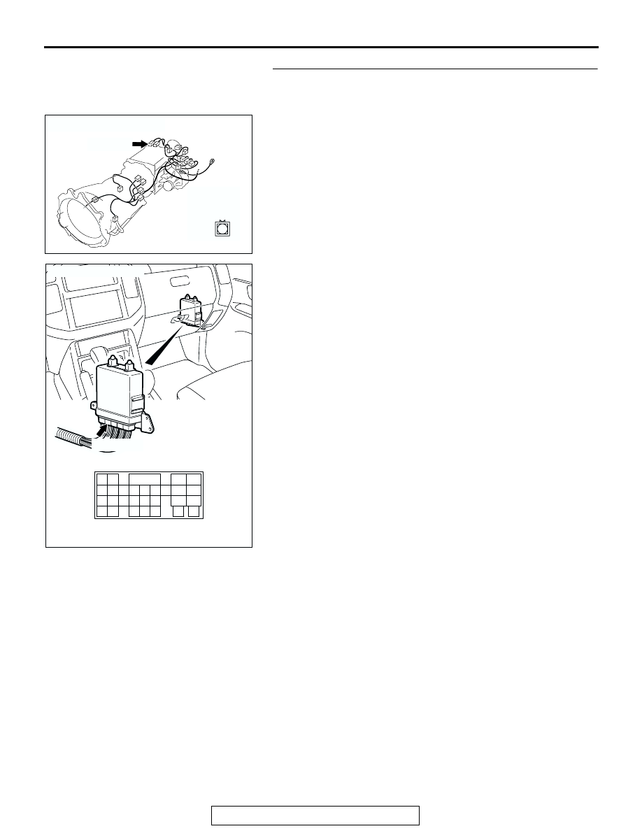
STEP 8. Check harness for short circuit to ground between 
4LLc detection switch connector C-05 terminal 1 and PCM 
connector D-133 terminal 55.
Q: Is the harness wire in good condition?

YES : Go to Step 9.
NO :  Repair or replace the harness wire.

AC204395

CONNECTOR : C-05

AG

C-05 (BR)

C-05

1

AC204681AD

CONNECTOR: D-133

D-133 (GR)

31 32

33 34

35 36 37 38 39 40 41 42 43
44 45 46 47 48 49

50 51

52 53

54 55 56

57 58

SYMPTOM PROCEDURES <AUTOMATIC TRANSMISSION>

TSB Revision

SYMPTOM PROCEDURES

23Ad-76

STEP 9. Using scan tool MB991502, check data list item 75: 
4LLc Detection Switch.

CAUTION

To prevent damage to scan tool MB991502, always turn the 
ignition switch to the "LOCK" (OFF) position before con-
necting or disconnecting scan tool MB991502.
(1) Connect scan tool MB991502 to the data link connector.
(2) Turn the ignition switch to the "ON" position.
(3) Set scan tool MB991502 to data reading mode for item 75, 

4LLc Detection Switch.

• When the transfer shift lever position is 4LLc, scan tool 

MB991502 display should be "ON."

• When the transfer shift lever position is other than 4LLc, 

scan tool MB991502 display should be "OFF."

(4) Turn the ignition switch to the "LOCK" (OFF) position.
Q: Is the switch operating properly?

YES : It can be assumed that this malfunction is intermittent. 

Refer to GROUP 00, How to Use Troubleshooting/
Inspection Service Points 

− How to Cope with 

Intermittent Malfunction 

P.00-6

.

NO :  Replace the PCM.

STEP 10. Measure the resistance at 4LLc detection switch 
connector C-05.
(1) Disconnect connector C-05 and measure at the switch side.
(2) Turn the ignition switch to the "ON" position.
(3) Transmission range should be "N" range.

(4) Check for the continuity between terminal 1 and ground.

• When the transfer shift lever position is 4LLc there 

should measure less than 2 ohms.

• When the transfer shift lever position is other than 4LLc 

there should be open circuit.

(5) Turn the ignition switch to the "LOCK" (OFF) position.
Q: Is the resistance 2 ohms?

YES : Go to Step 11.
NO :  Replace the 4LLc detection switch. Refer to GROUP 

23B, Transfer 

P.23B-103

.

ACX01539AD

MB991502

16-PIN

AC204395

CONNECTOR : C-05

AG

C-05 (BR)

C-05

1

AC204918

C-05 HARNESS CONNECTOR : 
4LLc DETECTION SWITCH SIDE

DA

1

SYMPTOM PROCEDURES <AUTOMATIC TRANSMISSION>

TSB Revision

SYMPTOM PROCEDURES

23Ad-77

STEP 11. Check PCM connector D-133 for loose, corroded 
or damaged terminals, or terminals pushed back in the 
connector.
Q: Are the connector and terminals in good condition?

YES : Go to Step 9.
NO :  Repair or replace the damaged components. Refer to 

GROUP 00E, Harness Connector Inspection 

P.00E-

2

.

AC204681AD

CONNECTOR: D-133

D-133 (GR)

31 32

33 34

35 36 37 38 39 40 41 42 43
44 45 46 47 48 49

50 51

52 53

54 55 56

57 58

SYMPTOM PROCEDURES <KEY INTERLOCK AND SHIFT LOCK MECHANISMS>

TSB Revision

SYMPTOM PROCEDURES

23Ad-78

SYMPTOM PROCEDURES 

<KEY INTERLOCK AND SHIFT LOCK MECHANISMS>

INSPECTION PROCEDURE 1: Selector Lever can be Moved from "P" to "R" Position without 
Depressing Brake Pedal when Ignition Key is at Positions other than "LOCK" (OFF) Position.

.

TECHNICAL DESCRIPTION (COMMENT)
Lock cam or shift lock cable may be defective.

.

TROUBLESHOOTING HINTS

• Malfunction of lock cam

• Malfunction of shift lock cable

DIAGNOSIS

STEP 1. Check the fit of the lock cam.

Q: Is the lock cam installed correctly?

YES : 

Go to Step 2.

NO : 

Install the lock cam correctly. Refer to 

P.23Aa-33

. When the brake pedal is 

released with the ignition key at other 
positions than "LOCK" (OFF) position, 
check that the selector lever can not be 
moved from "P" position to "R" position.

STEP 2. Check the lock cam.

Q: Is the lock cam in good condition?

YES : 

Go to Step 3.

NO : 

Replace the lock cam. Refer to 

P.23Aa-33

When the brake pedal is released with the 
ignition key at other positions than "LOCK" 
(OFF) position, check that the selector lever 
can not be moved from "P" position to "R" 
position.

STEP 3. Check the fit of the shift lock cable.

Q: Is the shift lock cable installed correctly?

YES : 

Go to Step 4.

NO : 

Install the shift lock cable correctly. Refer to 

P.23Aa-35

. When the brake pedal is 

released with the ignition key at other 
positions than "LOCK" (OFF) position, 
check that the selector lever can not be 
moved from "P" position to "R" position.

STEP 4. Check the shift lock cable.

Q: Is the shift lock cable in good condition?

YES : 

No action to be taken.

NO : 

Replace the shift lock cable. Refer to 

P.23Aa-35

. When the brake pedal is 

released with the ignition key at other 
positions than "LOCK" (OFF) position, 
check that the selector lever can not be 
moved from "P" position to "R" position.

INSPECTION PROCEDURE 2: Selector Lever cannot be Moved from "P" to "R" Position with Brake 
Pedal Depressed when Ignition Key is at Positions other than "LOCK" (OFF) Position.

.

TECHNICAL DESCRIPTION (COMMENT)
Selector lever assembly, shift lock cable, key inter-
lock cable, transmission control cable, or lock cam 
may be defective.

.

TROUBLESHOOTING HINTS

• Malfunction of selector lever assembly

• Malfunction of shift lock cable

• Malfunction of key interlock cable

• Malfunction of transmission control cable

• Malfunction of lock cam


Content   ..  989  990  991  992   ..