Mitsubishi Montero (2002-2004). Manual - part 989


  Index      Mitsubishi     Mitsubishi Montero - service repair manual 2002-2004 year


Search            


Content   ..  987  988  989  990   ..


Mitsubishi Montero (2002-2004). Manual - part 989


SYMPTOM PROCEDURES <AUTOMATIC TRANSMISSION>

TSB Revision

SYMPTOM PROCEDURES

23Ad-67

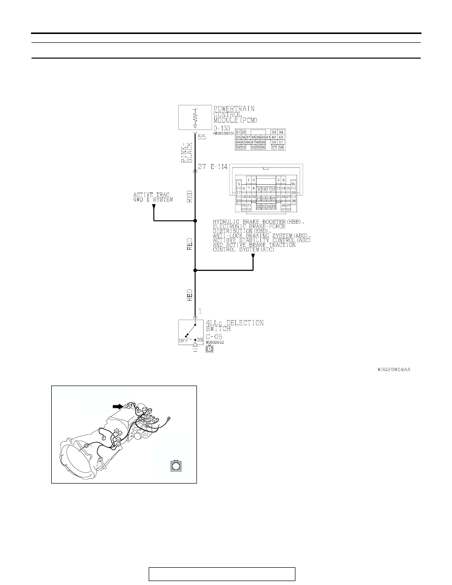
INSPECTION PROCEDURE 18: 4LLc Detection Switch System

AC205257AB

4LLc Detection Switch System Circuit

AC204395

CONNECTOR : C-05

AG

C-05 (BR)

C-05

1

SYMPTOM PROCEDURES <AUTOMATIC TRANSMISSION>

TSB Revision

SYMPTOM PROCEDURES

23Ad-68

.

CIRCUIT OPERATION

• A battery positive voltage is applied to the 4LLc 

detection switch output terminal (terminal 1) from 
the PCM (terminal 55) via the resistance in the 
unit.

• The 4LLc detection switch is grounded through 

the transfer case to the vehicle body.

.

COMMENT
If the transmission will not shift to 4th gear, or if it 
shifts to 4th gear when the transfer lever is in the 
"4LLc" position, the cause is probably a malfunction 
of the 4LLc detection switch.

.

TROUBLESHOOTING HINTS (The most likely 
causes for this case:)

• Malfunction of the 4LLc detection switch

• Damaged harness, connector

• Malfunction of the PCM

DIAGNOSIS

Required Special Tool:

• MB991502: Scan Tool (MUT-II)

AC204681AD

CONNECTOR: D-133

D-133 (GR)

31 32

33 34

35 36 37 38 39 40 41 42 43
44 45 46 47 48 49

50 51

52 53

54 55 56

57 58

AC204176

CONNECTOR : E-114

BD

38

28

16

33

22

10

31

19

7

1

18

30

29

17

5

6

21

20

32

8

2

9

25

13

3

24

23

3435

1112

27

26

3637

14

4

15

SYMPTOM PROCEDURES <AUTOMATIC TRANSMISSION>

TSB Revision

SYMPTOM PROCEDURES

23Ad-69

STEP 1. Using scan tool MB991502, check data list item 75: 
4LLc Detection Switch.

CAUTION

To prevent damage to scan tool MB991502, always turn the 
ignition switch to the "LOCK" (OFF) position before con-
necting or disconnecting scan tool MB991502.
(1) Connect scan tool MB991502 to the data link connector.
(2) Turn the ignition switch to the "ON" position.
(3) Set scan tool MB991502 to data reading mode for item 75, 

4LLc Detection Switch.

• When the transfer shift lever position is 4LLc, scan tool 

MB991502 display should be "ON."

• When the transfer shift lever position is other than 4LLc, 

scan tool MB991502 display should be "OFF."

(4) Turn the ignition switch to the "LOCK" (OFF) position.
Q: Is the switch operating properly?

YES : It can be assumed that this malfunction is intermittent. 

Refer to GROUP 00, How to Use Troubleshooting/
Inspection Service Points 

− How to Cope with 

Intermittent Malfunction 

P.00-6

.

NO :  Go to Step 2.

STEP 2. Check 4LLc detection switch connector C-05 for 
loose, corroded or damaged terminals, or terminals 
pushed back in the connector.
Q: Are the connector and terminals in good condition?

YES : Go to Step 3.
NO :  Repair or replace the damaged components. Refer to 

GROUP 00E, Harness Connector Inspection 

P.00E-

2

.

ACX01539AD

MB991502

16-PIN

AC204395

CONNECTOR : C-05

AG

C-05 (BR)

C-05

1

SYMPTOM PROCEDURES <AUTOMATIC TRANSMISSION>

TSB Revision

SYMPTOM PROCEDURES

23Ad-70

STEP 3. Measure the switch output voltage at 4LLc 
detection switch connector C-05.
(1) Disconnect connector C-05 and measure at the harness 

side.

(2) Turn the ignition switch to the "ON" position.

(3) Measure the voltage between terminal 1 and ground.

• The voltage should measure battery positive voltage.

(4) Turn the ignition switch to the "LOCK" (OFF) position.
Q: Is the measured voltage battery positive voltage?

YES : Go to Step 10.
NO :  Go to Step 4.

AC204395

CONNECTOR : C-05

AG

C-05 (BR)

C-05

1

AC204918 AO

C-05 HARNESS CONNECTOR : 
COMPONENT SIDE

1


Content   ..  987  988  989  990   ..