Mitsubishi Montero (2002-2004). Manual - part 966


  Index      Mitsubishi     Mitsubishi Montero - service repair manual 2002-2004 year


Search            


Content   ..  964  965  966  967   ..


Mitsubishi Montero (2002-2004). Manual - part 966


DIAGNOSTIC TROUBLE CODE PROCEDURES <TRANSFER>

TSB Revision

DIAGNOSTIC TROUBLE CODE PROCEDURES

23Ac-347

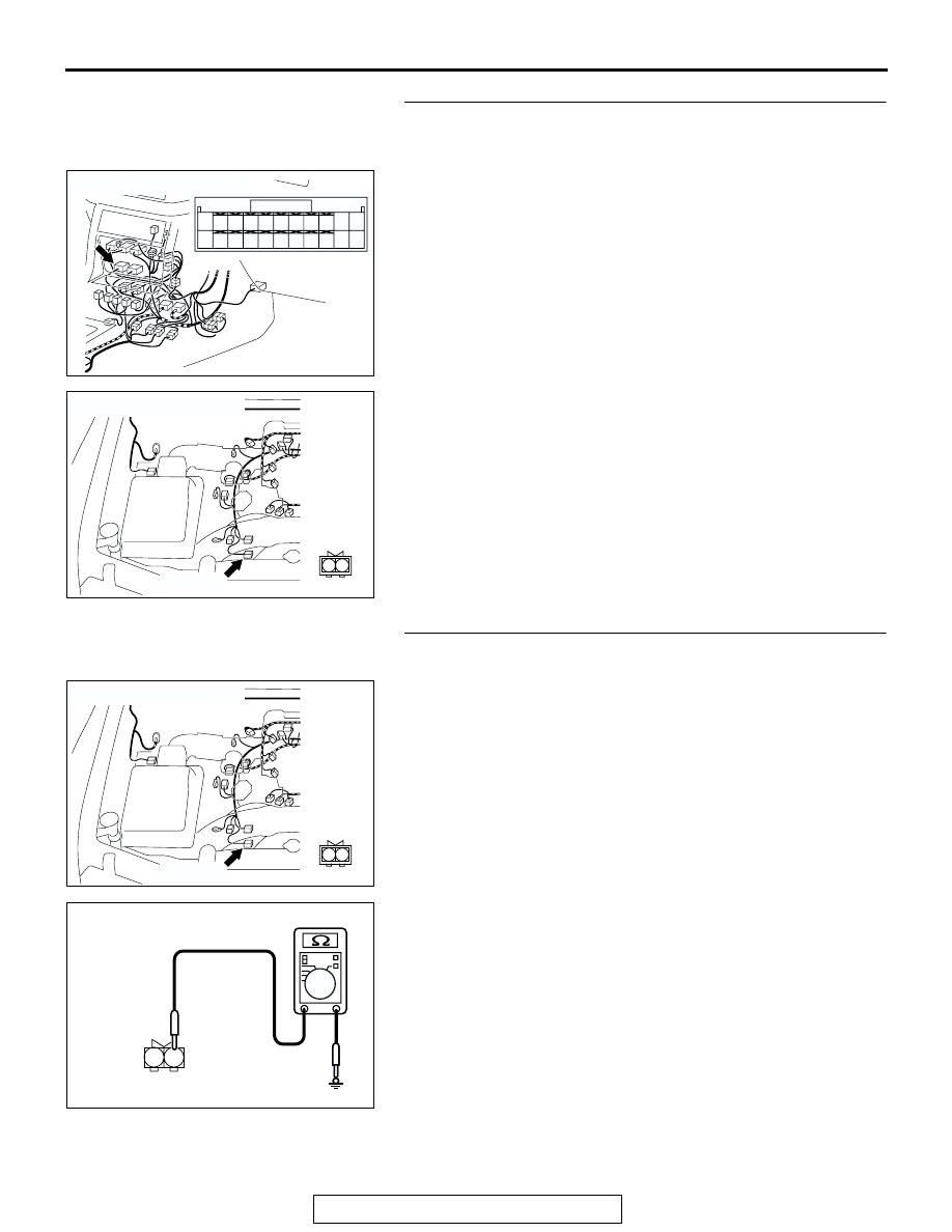
STEP 11. Check harness for open circuit between transfer-
ECU connector E-104 terminal 50 and free-wheel engage 
switch connector B-39 terminal 2.
Q: Is the harness wire in good condition?

YES : Go to Step 15.
NO :  Repair or replace the harness wire.

STEP 12. Measure the resistance at free-wheel engage 
switch.
(1) Disconnect connector B-39 and measure at the harness 

side.

(2) Measure the resistance between terminal 1 and ground.

• The resistance should measure less than 2 ohms.

Q: Is the measured resistance less than 2 ohms?

YES : Go to Step 15.
NO :  Go to Step 13.

AC204176

CONNECTOR : E-104

BA

51

40

3839

50

41

52

48

37

46

35

47

36

45

34

43

32

44

33

49

42

31

AC204168

CONNECTOR : B-39

AC

B-39 (GR)

2

1

AC204168

CONNECTOR : B-39

AC

B-39 (GR)

2

1

AC204918

B-39 HARNESS CONNECTOR : 
COMPONENT SIDE

CK

1

2

DIAGNOSTIC TROUBLE CODE PROCEDURES <TRANSFER>

TSB Revision

DIAGNOSTIC TROUBLE CODE PROCEDURES

23Ac-348

STEP 13. Check intermediate connector B-27 and free-
wheel engage switch connector B-39 for loose, corroded 
or damaged terminals, or terminals pushed back in the 
connector.
Q: Are the connectors and terminals in good condition?

YES : Go to Step 14.
NO :  Repair or replace the damaged components. Refer to 

GROUP 00E, Harness Connector Inspection 

P.00E-

2

.

STEP 14. Check harness for open circuit between free-
wheel engage switch connector B-39 terminal 1 and 
ground.
Q: Is the harness wire in good condition?

YES : Go to Step 15.
NO :  Repair or replace the harness wire.

AC204169

CONNECTOR : B-27

AD

B-27 (B)

8

4

7

3

5

1

6

2

AC204168

CONNECTOR : B-39

AC

B-39 (GR)

2

1

AC204168

CONNECTOR : B-39

AC

B-39 (GR)

2

1

DIAGNOSTIC TROUBLE CODE PROCEDURES <TRANSFER>

TSB Revision

DIAGNOSTIC TROUBLE CODE PROCEDURES

23Ac-349

STEP 15. Using scan tool MB991502, check data list item 
38: Free-wheel Engage Switch.

CAUTION

To prevent damage to scan tool MB991502, always turn the 
ignition switch to the "LOCK" (OFF) position before con-
necting or disconnecting scan tool MB991502.
(1) Connect scan tool MB991502 to the data link connector.
(2) Turn the ignition switch to the "ON" position.
(3) Transmission range should be "N" range.
(4) See scan tool MB991502 to data reading mode for item 38, 

Free-wheel Engage Switch.

• When the transfer shift lever position is other than 2H, 

the display should be "ON."

• When the transfer shift lever position is 2H, the display 

should be "OFF."

(5) Turn the ignition switch to the "LOCK" (OFF) position.
Q: Is the switch operating properly?

YES : It can be assumed that this malfunction is intermittent. 

Refer to GROUP 00, How to Use Troubleshooting/
Inspection Service Points 

− How to Cope with 

Intermittent Malfunction 

P.00-6

.

NO :  Replace the transfer-ECU.

DTC 41: Shift Actuator System (Short/Open Circuit)

ACX01539AD

MB991502

16-PIN

AC100559

Shift Actuator System Circuit

AB

AC204395

CONNECTOR : C-09

AH

C-09 (GR)

2

1

AC204176

CONNECTOR : E-109

BB

11 12

25

24

13

26

9

22

7

6

20

19

8

21

10

23

5

4

17

2

1

15

14

3

16

18

DIAGNOSTIC TROUBLE CODE PROCEDURES <TRANSFER>

TSB Revision

DIAGNOSTIC TROUBLE CODE PROCEDURES

23Ac-350

.

CIRCUIT OPERATION
When voltage is applied to the shift actuator terminal 
2 from the transfer-ECU, the motor turns to the nor-
mal direction and the drive mode is shifted in the 
order of 2H 

→ 4H → 4HLc → 4LLc. When voltage is 

applied to the shift actuator terminal 1, the motor 
turns to the reverse direction and the drive mode is 
shifted in the order of 4LLc 

→ 4HLc → 4H → 2H.

.

DTC SET CONDITIONS
In the case that the transfer-ECU terminal voltage is 
more than the main relay voltage (90% of specified 
voltage) or lower than the main relay voltage (10% of 
specified voltage) when the shift is not operated, 
DTC 41 is set as the open circuit or the short circuit 
of the shift actuator system.

.

TROUBLESHOOTING HINTS (The most likely 
causes for this code to be set are:)

• Malfunction of the shift actuator

• Damaged harness, connector

• Malfunction of the transfer-ECU

DIAGNOSIS

Required Special Tool:

• MB991502: Scan Tool (MUT-II)

STEP 1. Using scan tool MB991502, check data list item 12: 
Shift Actuator Voltage.

CAUTION

To prevent damage to scan tool MB991502, always turn the 
ignition switch to the "LOCK" (OFF) position before con-
necting or disconnecting scan tool MB991502.
(1) Connect scan tool MB991502 to the data link connector.
(2) Turn the ignition switch to the "ON" position.
(3) Transmission range should be "N" range.
(4) Set scan tool MB991502 to data reading mode for item 12, 

Shift Actuator Voltage.

• When the operating transfer shift lever 2H → 4H, 4H → 

4HLc or 4HLc 

→ 4LLc, the display should be 1/2 battery 

voltage 

→ battery positive voltage → 1.0 volt or less → 

1/2 battery voltage.

• When the operating transfer shift lever 4LLc → 4HLc, 

4HLc 

→ 4H or 4H → 2H, the display should be 1/2 bat-

tery voltage 

→ 1.0 volt or less → 1/2 battery voltage.

(5) Turn the ignition switch to the "LOCK" (OFF) position.
Q: Is the actuator operating properly?

YES : It can be assumed that this malfunction is intermittent. 

Refer to GROUP 00, How to Use Troubleshooting/
Inspection Service Points 

− How to Cope with 

Intermittent Malfunction

P.00-6

 .

NO :  Go to Step 2.

ACX01539AD

MB991502

16-PIN


Content   ..  964  965  966  967   ..