Mitsubishi Montero (2002-2004). Manual - part 948


  Index      Mitsubishi     Mitsubishi Montero - service repair manual 2002-2004 year


Search            


Content   ..  946  947  948  949   ..


Mitsubishi Montero (2002-2004). Manual - part 948


DIAGNOSTIC TROUBLE CODE PROCEDURES <TRANSFER>

TSB Revision

DIAGNOSTIC TROUBLE CODE PROCEDURES

23Ac-275

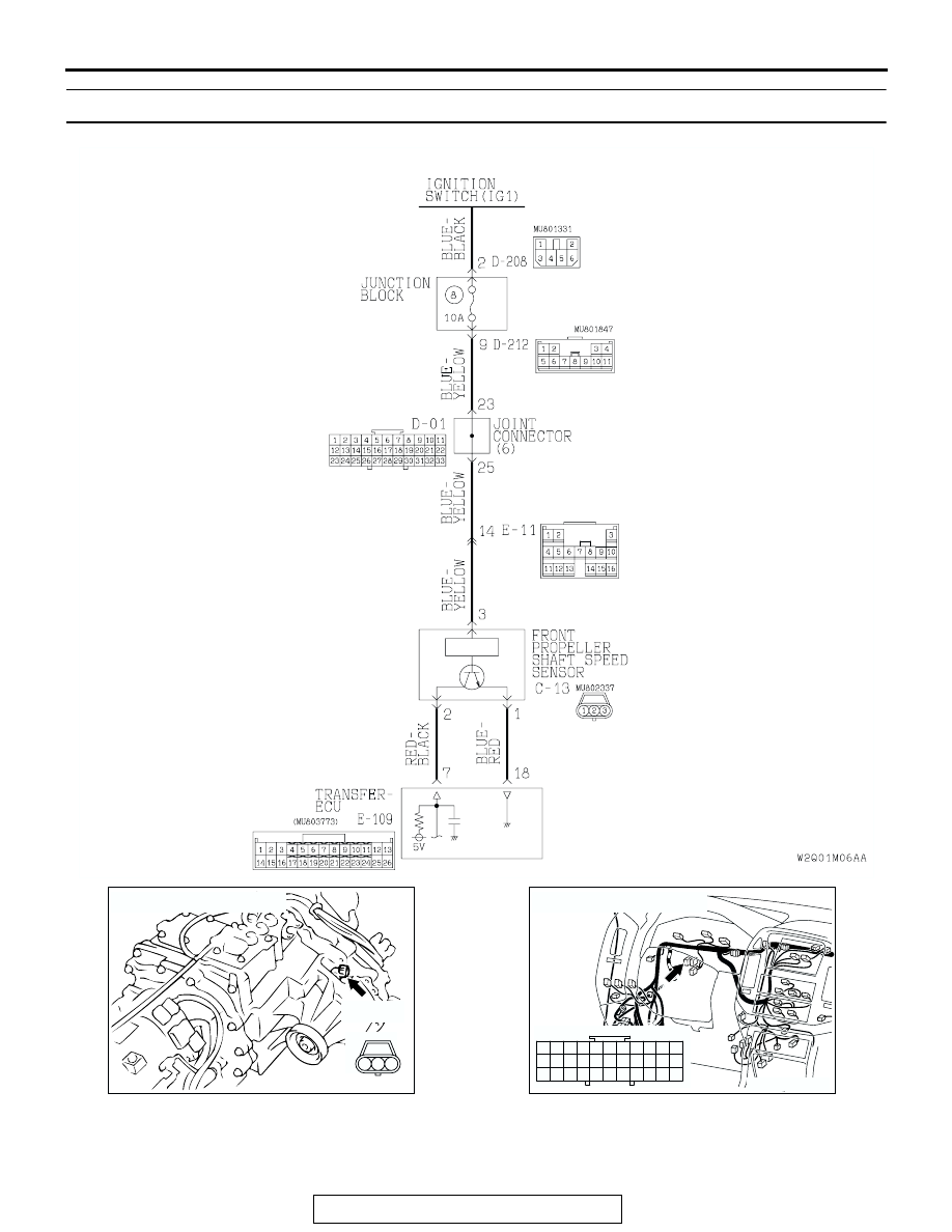
DTC 22, 23: Front Propeller Shaft Speed Sensor System

AC100558

Front Propeller Shaft Speed Sensor System Circuit

AB

AC204752

CONNECTOR : C-13

AB

2 3

1

C-13 (B)

AC204170

CONNECTOR : D-01

CD

9 10

8

6 7

31 32

30

29

18 19 20 21

5

4

2

1

3

27

26

24

23

25

12 13 14 15 16 17

28

11
22
33

DIAGNOSTIC TROUBLE CODE PROCEDURES <TRANSFER>

TSB Revision

DIAGNOSTIC TROUBLE CODE PROCEDURES

23Ac-276

.

CIRCUIT OPERATION

• The front propeller shaft speed sensor generates 

⇔ 5 volts pulse signal when the front propeller 

shaft rotates. The pulse signal frequency 
increases with a rise in front propeller shaft 
speed.

• The front propeller shaft speed sensor is con-

nected to the transfer-ECU (terminals 7 and 18) 
via the front propeller shaft speed sensor connec-
tor (terminals 1 and 2).

• The transfer-ECU detects the front propeller shaft 

speed by the signal input to terminal 7.

• The front propeller shaft speed sensor generates 

the pulse signal as the hole in the front output 
shaft pass the magnetic tip of the sensor.

.

DTC SET CONDITIONS
In the case that the input signal from the front propel-
ler shaft speed sensor is not input during the shift 
from 2WD to 4WD, the DTC 22 is set as the open cir-
cuit or the short circuit of the front propeller shaft 
speed sensor. In the case that the input signal from 
the front propeller shaft speed sensor is unstable 
when the engage switch is ON condition, the code 
DTC 23 is set as the open circuit or the short circuit 
of the front propeller shaft speed sensor.

.

TROUBLESHOOTING HINTS (The most likely 
causes for this code to be set are:)

• Malfunction of the front propeller shaft speed 

sensor circuit

• Malfunction of the front output shaft

• Damaged harness, connector

• Malfunction of the transfer-ECU

DIAGNOSIS

Required Special Tool:

• MB991502: Scan Tool (MUT-II)

AC204191

CONNECTORS : D-208, D-212

5 6

2

4

3

1

JUNCTION BLOCK
(FRONT VIEW)

3

10

9

4

11

8

7

1

5

2

6

D-208

D-208

D-212

D-212

AS

AC204194

CONNECTORS : E-11, E-109

E-109

E-109

E-11

E-11

AW

3

10

16

9

7 8

6

1

4

2

5

11

14

1213

15

11 12

25

24

13

26

9

22

7

6

20

19

8

21

10

23

5

4

17

2

1

15

14

3

16

18

DIAGNOSTIC TROUBLE CODE PROCEDURES <TRANSFER>

TSB Revision

DIAGNOSTIC TROUBLE CODE PROCEDURES

23Ac-277

STEP 1. Using scan tool MB991502, check data list item 02: 
Front Propeller Shaft Speed Sensor.

CAUTION

To prevent damage to scan tool MB991502, always turn the 
ignition switch to the "LOCK" (OFF) position before con-
necting or disconnecting scan tool MB991502.
(1) Connect scan tool MB991502 to the data link connector.
(2) Start the engine.
(3) Set scan tool MB991502 to data reading mode for item 02, 

Front Propeller Shaft Speed Sensor.

• When driving at constant speed of 30 km/h (19 mph), 

the display should be "30 km/h (19 mph)."

(4) Turn the ignition switch to the "LOCK" (OFF) position.
Q: Is the sensor operating properly?

YES : It can be assumed that this malfunction is intermittent. 

Refer to GROUP 00, How to Use Troubleshooting/
Inspection Service Points 

− How to Cope with 

Intermittent Malfunction 

P.00-6

.

NO :  Go to Step 2.

STEP 2. Measure the power supply voltage at front 
propeller shaft speed sensor connector C-13.
(1) Disconnect connector C-13 and measure at the harness 

side.

(2) Turn the ignition switch to the "ON" position.

(3) Measure the voltage between terminal 3 and ground.

• The voltage should measure battery positive voltage.

(4) Turn the ignition switch to the "LOCK" (OFF) position.
Q: Is the measured voltage battery positive voltage?

YES : Go to Step 5.
NO :  Go to Step 3.

ACX01539AD

MB991502

16-PIN

AC204752

CONNECTOR : C-13

AB

2 3

1

C-13 (B)

AC204918

3

1

2

AC204918 AV

C-13 HARNESS CONNECTOR : 
COMPONENT SIDE

DIAGNOSTIC TROUBLE CODE PROCEDURES <TRANSFER>

TSB Revision

DIAGNOSTIC TROUBLE CODE PROCEDURES

23Ac-278

STEP 3. Check joint connector D-01, junction block 
connector D-212 and intermediate connector E-11 for 
loose, corroded or damaged terminals, or terminals 
pushed back in the connector.
Q: Are the connectors and terminals in good condition?

YES : Go to Step 4.
NO :  Repair or replace the damaged components. Refer to 

GROUP 00E, Harness Connector Inspection 

P.00E-

2

.

AC204170

CONNECTOR : D-01

CD

9 10

8

6 7

31 32

30

29

18 19 20 21

5

4

2

1

3

27

26

24

23

25

12 13 14 15 16 17

28

11
22
33

AC204173

CONNECTOR : D-212

AZ

3

10

9

4

11

8

7

1

5

2

6

JUNCTION BLOCK
(FRONT VIEW)

AC204176

CONNECTOR : E-11

AZ

3

10

16

9

7 8

6

1

4

2

5

11

14

1213

15


Content   ..  946  947  948  949   ..