Mitsubishi Montero (2002-2004). Manual - part 946


  Index      Mitsubishi     Mitsubishi Montero - service repair manual 2002-2004 year


Search            


Content   ..  944  945  946  947   ..


Mitsubishi Montero (2002-2004). Manual - part 946


DIAGNOSTIC TROUBLE CODE PROCEDURES <TRANSFER>

TSB Revision

DIAGNOSTIC TROUBLE CODE PROCEDURES

23Ac-267

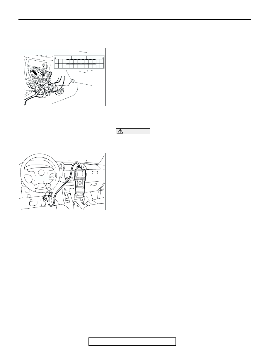
STEP 5. Check transfer-ECU connector E-109 for loose, 
corroded or damaged terminals, or terminals pushed back 
in the connector.
Q: Are the connector and terminals in good condition?

YES : Go to Step 6.
NO :  Repair or replace the damaged components. Refer to 

GROUP 00E, Harness Connector Inspection 

P.00E-

2

.

STEP 6. Using scan tool MB991502, check data list item 09: 
Ignition switch power supply.

CAUTION

To prevent damage to scan tool MB991502, always turn the 
ignition switch to the "LOCK" (OFF) position before con-
necting or disconnecting scan tool MB991502.
(1) Connect scan tool MB991502 to the data link connector.
(2) Turn the ignition switch to the "ON" position.
(3) Set scan tool MB991502 to data reading mode for item 09, 

Ignition Switch Power Supply.

• The voltage should equal battery positive voltage.

(4) Turn the ignition switch to the "LOCK" (OFF) position.
Q: Is the measured voltage equal battery positive voltage?

YES : It can be assumed that this malfunction is intermittent. 

Refer to GROUP 00, How to Use Troubleshooting/
Inspection Service Points 

− How to Cope with 

Intermittent Malfunction 

P.00-6

.

NO :  Replace the transfer-ECU.

AC204176

CONNECTOR : E-109

BB

11 12

25

24

13

26

9

22

7

6

20

19

8

21

10

23

5

4

17

2

1

15

14

3

16

18

ACX01539AD

MB991502

16-PIN

DIAGNOSTIC TROUBLE CODE PROCEDURES <TRANSFER>

TSB Revision

DIAGNOSTIC TROUBLE CODE PROCEDURES

23Ac-268

DTC 13: Main Relay System (Inside of ECU)

.

CIRCUIT OPERATION
The power supplied from the ignition switch is distrib-
uted to each part of ECU through the main relay 
located inside of ECU.

.

DTC SET CONDITIONS
When the voltage at main relay OFF is 6 volts and 
over, or the voltage at main relay ON is 6 volts and 
less, the DTC 13 is set as the main relay malfunction.

.

TROUBLESHOOTING HINTS (The most likely 
causes for this code to be set:)

• Malfunction of the transfer-ECU

DIAGNOSIS

Replace the transfer-ECU.
Q: Is the malfunction eliminated?

YES : The procedure is complete. (If no malfunction is not 

found an intermittent malfunction is suspected. Refer 
to GROUP 00, How to Use Troubleshooting/
Inspection Service Points 

− How to Cope with 

Intermittent Malfunction 

P.00-6

.)

NO :  Replace the PCM.

DIAGNOSTIC TROUBLE CODE PROCEDURES <TRANSFER>

TSB Revision

DIAGNOSTIC TROUBLE CODE PROCEDURES

23Ac-269

DTC 21: Accelerator Pedal Position Sensor System

AC205258AB

Accelrator Pedal Position Sensor System Circuit

AC204681AB

CONNECTOR: D-135

D-135 (GR)

91 92

93

101

94 95

96 97 98 99 100

102103

104

105106

107108 109

110 111112

113114

115116 117

118 119120

AC203914

AD

STEERING
SHAFT

CONNECTOR : D-138

D-138 (GR)

1

3

2

4

6

5

7 8

DIAGNOSTIC TROUBLE CODE PROCEDURES <TRANSFER>

TSB Revision

DIAGNOSTIC TROUBLE CODE PROCEDURES

23Ac-270

.

CIRCUIT OPERATION

• When the throttle valve shaft rotates from the idle 

position to the fully opened position, the resis-
tance between the accelerator pedal position 
sensor output terminal (terminal 6) and ground 
terminal (terminal 7) will increase according to 
the rotation.

• With the ignition switch in the "ON" position. Volt-

age at pin 5 increases from approximately 0.7 
volt at closed throttle, to approximately 5 volts at 
wide open throttle.

.

DTC SET CONDITIONS
If accelerator pedal position sensor output voltage is 
0.2 volt or lower at times other than when the engine 
is idling, the output is judged to be too low and DTC 
21 is set.

.

TROUBLESHOOTING HINTS (The most likely 
causes for this code to be set are:)

• Malfunction of the accelerator pedal position sen-

sor circuit

• Damaged harness, connector

• Malfunction of the transfer-ECU

AC204194

CONNECTORS : E-109, E-114

BH

11 12

25

24

13

26

9

22

7

6

20

19

8

21

10

23

5

4

17

2

1

15

14

3

16

18

E-109

E-114

E-109

E-114

38

28

16

33

22

10

31

19

7

1

18

30

29

17

5

6

21

20

32

8

2

9

25

13

3

24

23

3435

1112

27

26

3637

14

4

15


Content   ..  944  945  946  947   ..