Mitsubishi Montero (2002-2004). Manual - part 943


  Index      Mitsubishi     Mitsubishi Montero - service repair manual 2002-2004 year


Search            


Content   ..  941  942  943  944   ..


Mitsubishi Montero (2002-2004). Manual - part 943


DIAGNOSTIC TROUBLE CODE PROCEDURES <AUTOMATIC TRANSMISSION>

TSB Revision

DIAGNOSTIC TROUBLE CODE PROCEDURES

23Ac-255

.

CIRCUIT OPERATION
If a fail-safe is triggered while driving forward, the 
PCM flashes the "N" range light once per second 
(triggered fail-safe). The PCM does this by switching 
battery positive voltage to terminal 75.

.

DTC SET CONDITIONS
If the PCM detects a fail-safe condition, it will attempt 
to illuminate the "N" range light. The PCM sends a 12 
volts pulse for 60 

− 180 ms. If it does not detect a 

voltage drop during the pulse, it waits about 60 sec-
onds and pulses 12 volts again for 60 

− 180 ms. If 

the PCM does no detect the voltage drop before the 
ignition switch is turned the "LOCK" (OFF), the PCM 
will consider it as an short circuit of the "N" range 
light circuit and DTC 56 is set.

.

TROUBLESHOOTING HINTS (The most likely 
causes for this code to be set are:)

• Defective "N" range light bulb

• Damaged harness, connector

• Malfunction of the PCM
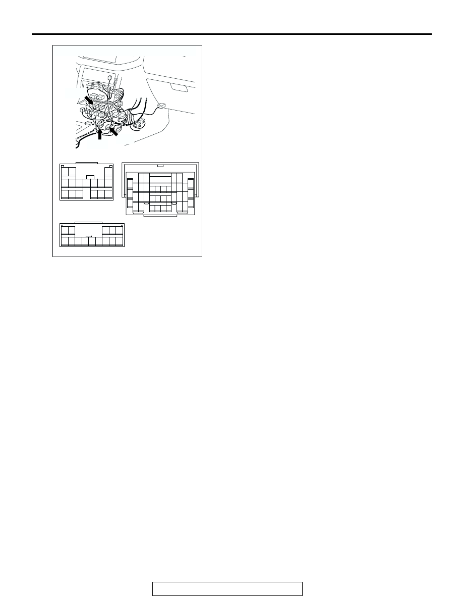
AC204194

CONNECTORS : E-11, E-113, E-114

E-113

E-113

E-11

E-11

BD

E-114

E-114

3

10

16

9

7 8

6

1

4

2

5

11

14

1213

15

1

6

2

7 8 9 10 11 12 13 14

3 4 5

38

28

16

33

22

10

31

19

7

1

18

30

29

17

5

6

21

20

32

8

2

9

25

13

3

24

23

3435

1112

27

26

3637

14

4

15

DIAGNOSTIC TROUBLE CODE PROCEDURES <AUTOMATIC TRANSMISSION>

TSB Revision

DIAGNOSTIC TROUBLE CODE PROCEDURES

23Ac-256

DIAGNOSIS

Required Special Tool:

• MB991502: Scan Tool (MUT-II)

STEP 1. Check the "N" range light bulb.
(1) Turn the ignition switch to the "ON" position.
(2) Move the selector lever to "N" position.

• The "N" range light in the combination meter illuminates.

(3) Turn the ignition switch to the "LOCK" (OFF) position.
Q: Does the "N" range light illuminate?

YES : Go to Step 6.
NO :  Go to Step 2.

STEP 2. Check the "N" range light bulb.
(1) Remove the combination meter. Refer to GROUP 54A, 

Chassis Electrical 

− Combination Meters Assembly and 

Vehicle Speed Sensor 

P.54A-65

.

(2) Check the "N" range light bulb.
Q: Is the bulb in good condition?

YES : Go to Step 3.
NO :  Replace the "N" range light bulb.

STEP 3. Check combination meter connectors D-03 and D-
32 for loose, corroded or damaged terminals, or terminals 
pushed back in the connector.
Q: Are the connectors and terminals in good condition?

YES : Go to Step 4.
NO :  Repair or replace the damaged components. Refer to 

GROUP 00E, Harness Connector Inspection 

P.00E-

2

.

AC204188

CONNECTORS : D-03, D-32

D-03 (GR)

AX

D-32 (GR)

D-32

D-03

58

57

67

66

56

54 55

64

59

53

52

62

61

63

65

60

51

10

9

23

22

12

11

25

24

8

6 7

20

13

5

4

18

17

19

21

16

3

2

15

14

1

DIAGNOSTIC TROUBLE CODE PROCEDURES <AUTOMATIC TRANSMISSION>

TSB Revision

DIAGNOSTIC TROUBLE CODE PROCEDURES

23Ac-257

STEP 4. Measure the resistance at combination meter 
connector D-03.
(1) Disconnect connector D-03 and measure at the harness 

side.

(2) Measure the resistance between terminal 57 and ground.

• The measured resistance should be less than 2 ohms.

Q: Is the measured resistance less than 2 ohms?

YES : Go to Step 7.
NO :  Go to Step 5.

STEP 5. Check combination meter connector D-03 and 
joint connector D-30 for loose, corroded or damaged 
terminals, or terminals pushed back in the connector.
Q: Are the connectors and terminals in good condition?

YES : Go to Step 6.
NO :  Repair or replace the damaged components. Refer to 

GROUP 00E, Harness Connector Inspection 

P.00E-

2

.

AC204170

CONNECTOR : D-03

CE

D-03 (GR)

58

57

67

66

56

54 55

64

59

53

52

62

61

63

65

60

51

AC204918

D-03 HARNESS CONNECTOR :
COMPONENT SIDE

DK

51

52

61 60

53

54

56

57

55

63

66 65 64

59

62

58

67

AC204188

CONNECTORS : D-03, D-30

D-03 (GR)

D-03

D-30

D-30

AU

9 10

8

6 7

31 32

30

29

18 19 20 21

5

4

2

1

3

27

26

24

23

25

12 13 14 15 16 17

28

11
22
33

58

57

67

66

56

54 55

64

59

53

52

62

61

63

65

60

51

DIAGNOSTIC TROUBLE CODE PROCEDURES <AUTOMATIC TRANSMISSION>

TSB Revision

DIAGNOSTIC TROUBLE CODE PROCEDURES

23Ac-258

STEP 6. Check the harness for open circuit or damage 
between combination meter connector D-03 terminal 57 
and body ground.
Q: Is the harness wire in good condition?

YES : Go to Step 9.
NO :  Repair or replace the harness wire.

AC204170

CONNECTOR : D-03

CE

D-03 (GR)

58

57

67

66

56

54 55

64

59

53

52

62

61

63

65

60

51


Content   ..  941  942  943  944   ..