Mitsubishi Montero (2002-2004). Manual - part 916


  Index      Mitsubishi     Mitsubishi Montero - service repair manual 2002-2004 year


Search            


Content   ..  914  915  916  917   ..


Mitsubishi Montero (2002-2004). Manual - part 916


DIAGNOSTIC TROUBLE CODE PROCEDURES <AUTOMATIC TRANSMISSION>

TSB Revision

DIAGNOSTIC TROUBLE CODE PROCEDURES

23Ac-147

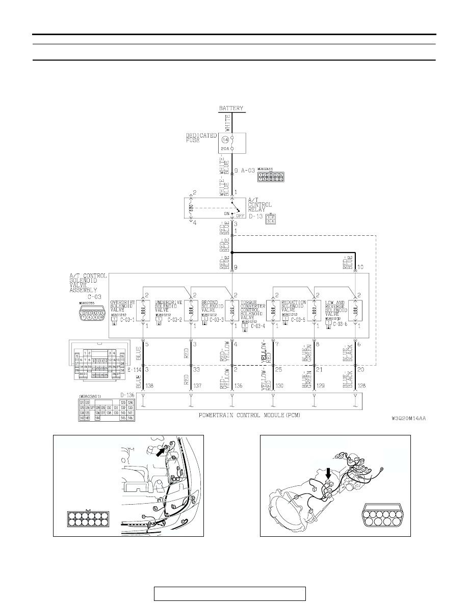
DTC 31: Low-Reverse Solenoid Valve System

AC205195 AB

Solenoid Valve System Circuit

AC204167

CONNECTOR : A-03

AT

A-03 (B)

6

12

5

3 4

2

1

9 10

8

7

11

AC204395

CONNECTOR : C-03

AE

C-03 (B)

6

10

4

9

5

3

8

2

7

1

DIAGNOSTIC TROUBLE CODE PROCEDURES <AUTOMATIC TRANSMISSION>

TSB Revision

DIAGNOSTIC TROUBLE CODE PROCEDURES

23Ac-148

.

CIRCUIT OPERATION

• The A/T control relay supplies battery positive 

voltage to the solenoid valve assembly (terminals 
9 and 10).

• The solenoid valve closes when energized (on), 

and opens when not energized (off). The PCM 
energizes the solenoid valve based on input data 
from sensors such as the APP Sensor, Transmis-
sion Range Switch, Stoplight Switch, Vehicle 
Speed Sensor, Input Shaft Speed Sensor, Output 
Shaft Speed Sensor, and Transmission Fluid 
Temperature Sensor.

AC204749

1
2

CONNECTORS : C-03-1, C-03-2, C-03-3
                             C-03-4, C-03-5, C-03-6

C-03-1

C-03-1

1
2

C-03-2

1
2

C-03-3

1
2

C-03-4

1
2

C-03-5

1
2

C-03-6

C-03-2

C-03-3

AC

C-03-4

C-03-6

C-03-5

AC204750

CONNECTOR : D-13

AB

PCM

1
3 4

2

AC204681AD

CONNECTOR: D-136

D-136 (GR)

121 122

123

124

125 126 127 128 129 130

131 132

133

134 135

136 137 138

139 140

141

142 143

144

145

146

AC204176

CONNECTOR : E-114

BD

38

28

16

33

22

10

31

19

7

1

18

30

29

17

5

6

21

20

32

8

2

9

25

13

3

24

23

3435

1112

27

26

3637

14

4

15

DIAGNOSTIC TROUBLE CODE PROCEDURES <AUTOMATIC TRANSMISSION>

TSB Revision

DIAGNOSTIC TROUBLE CODE PROCEDURES

23Ac-149

• The PCM provides the ground to energize the 

solenoid. The amount of time that the circuit is 
grounded is displayed on scan tool MB991502 in 
percent.

• When the solenoid is energized or de-energized, 

fluid passes through the valve body and transmis-
sion passages to apply and release components.

.

DTC SET CONDITIONS
If the resistance value for the low-reverse solenoid 
valve circuit is greater than 3.5 

Ω (open) or less than 

2.6 

Ω (short) for 4 seconds, DTC 31 is set. The trans-

mission is locked into 3rd gear as a fail-safe mea-
sure, and the "N" range light flashes once per 
second.

.

TROUBLESHOOTING HINTS (The most likely 
causes for this code to be set are:)

• Malfunction of low-reverse solenoid valve

• Damaged harness, connector

• Malfunction of the PCM

DIAGNOSIS

Required Special Tool:

• MB991502: Scan Tool (MUT-II)

STEP 1. Using scan tool MB991502, check actuator test 
item 01: Low-Reverse Solenoid Valve.

CAUTION

To prevent damage to scan tool MB991502, always turn the 
ignition switch to the "LOCK" (OFF) position before con-
necting or disconnecting scan tool MB991502.
(1) Connect scan tool MB991502 to the data link connector.
(2) Turn the ignition switch to the "ON" position.
(3) Set scan tool MB991502 to actuator test mode for item 01, 

Low-Reverse Solenoid Valve.

• An audible clicking or buzzing should be heard when the 

low-reverse solenoid valve is energized.

(4) Turn the ignition switch to the "LOCK" (OFF) position.
Q: Is the solenoid valve operating properly?

YES : It can be assumed that this malfunction is intermittent. 

Refer to GROUP 00, How to Use Troubleshooting/
Inspection Service Points 

− How to Cope with 

Intermittent Malfunctions 

P.00-6

.

NO :  Go to Step 2.

STEP 2. Using scan tool MB991502, read the A/T 
diagnostic trouble code.
(1) Connect scan tool MB991502 to the data link connector.
(2) Turn the ignition switch to the "ON" position.
(3) Check for A/T diagnostic trouble code.
(4) Turn the ignition switch to the "LOCK" (OFF) position.
Q: Is DTC 54 set? (DTC 54 may be set along with multiple 

DTCs.)
YES : 
Refer to 

P.23Ac-237

 DTC 54: A/T Control Relay 

System.

NO :  Go to Step 3.

ACX01539AD

MB991502

16-PIN

ACX01539AD

MB991502

16-PIN

DIAGNOSTIC TROUBLE CODE PROCEDURES <AUTOMATIC TRANSMISSION>

TSB Revision

DIAGNOSTIC TROUBLE CODE PROCEDURES

23Ac-150

STEP 3. Using scan tool MB991502, read the A/T 
diagnostic trouble code.
(1) Connect scan tool MB991502 to the data link connector.
(2) Turn the ignition switch to the "ON" position.
(3) Check for A/T diagnostic trouble code.
(4) Turn the ignition switch to the "LOCK" (OFF) position.
Q: Are DTC 35 and DTC 36 set? (Multiple DTCs may be set.)

YES : Go to Step 8.
NO :  Go to Step 4.

STEP 4. Measure the low-reverse solenoid valve resistance 
at A/T control solenoid valve assembly connector C-03.
(1) Disconnect connector C-03 and measure at the solenoid 

valve side.

(2) Measure the resistance between solenoid valve assembly 

connector C-03 terminals 6 and 10.

Resistance value: 2.7 

 3.4 ohms [at 20°C (68°F)]

Q: Is the measured resistance 2.7 

 3.4 ohms [at 20°

(68

°F)]?

YES : Go to Step 6.
NO :  Go to Step 5.

ACX01539AD

MB991502

16-PIN

AC204395

CONNECTOR : C-03

AE

C-03 (B)

6

10

4

9

5

3

8

2

7

1

AC204918

C-03 HARNESS CONNECTOR : 
SOLENOID VALVE SIDE

CW

6

10

4

9

5

3

8

2

7

1


Content   ..  914  915  916  917   ..