Mitsubishi Montero (2002-2004). Manual - part 900


  Index      Mitsubishi     Mitsubishi Montero - service repair manual 2002-2004 year


Search            


Content   ..  898  899  900  901   ..


Mitsubishi Montero (2002-2004). Manual - part 900


DIAGNOSTIC TROUBLE CODE PROCEDURES <AUTOMATIC TRANSMISSION>

TSB Revision

DIAGNOSTIC TROUBLE CODE PROCEDURES

23Ac-83

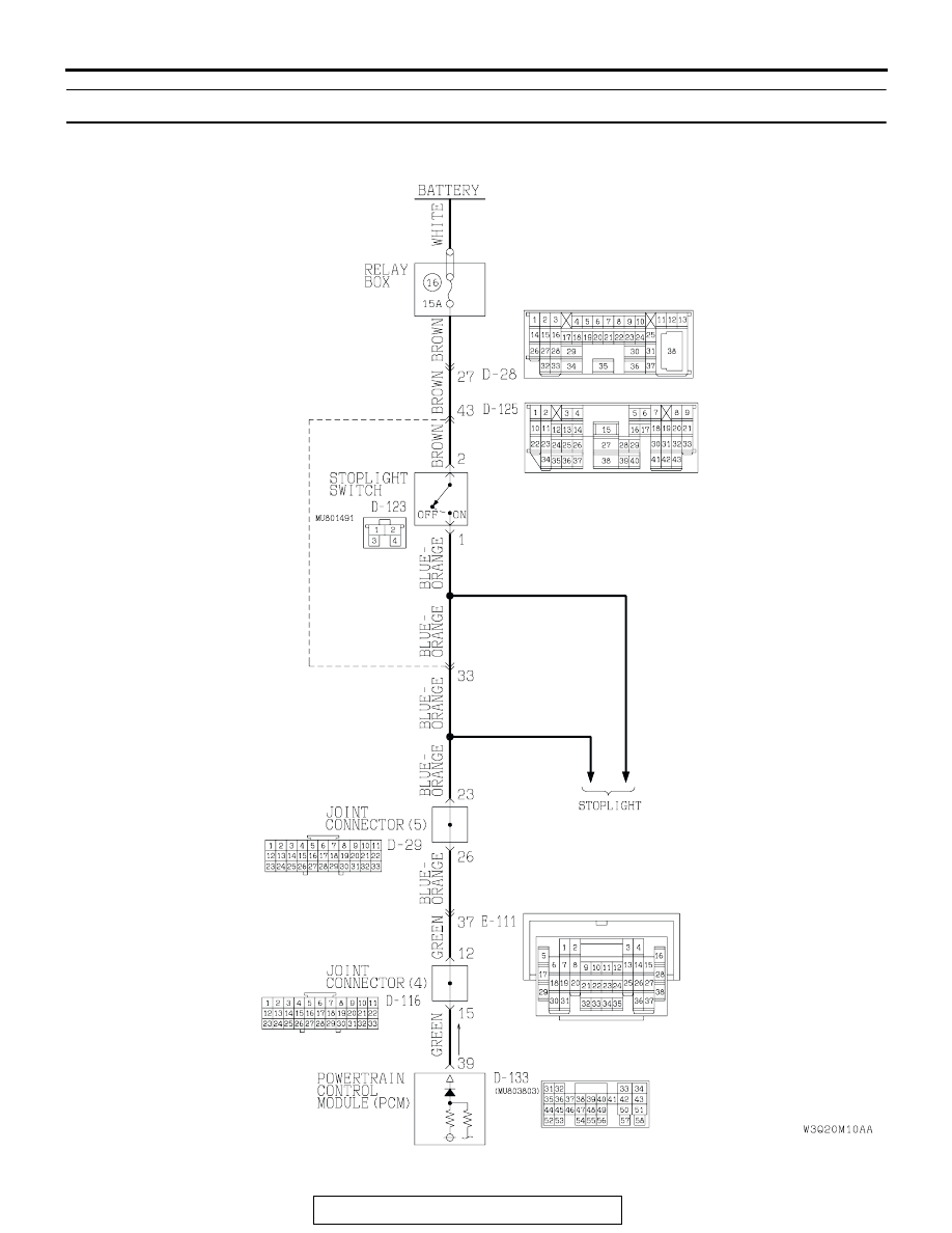
DTC 26: Stoplight Switch System

AC205191AB

Stoplight Switch System Circuit

DIAGNOSTIC TROUBLE CODE PROCEDURES <AUTOMATIC TRANSMISSION>

TSB Revision

DIAGNOSTIC TROUBLE CODE PROCEDURES

23Ac-84

.

CIRCUIT OPERATION

• Battery positive voltage is supplied to the stop-

light switch (terminal 2).

• When the brake pedal is depressed, battery posi-

tive voltage is applied to the PCM (terminal 39).

.

DTC SET CONDITIONS
If the stoplight switch is on for five minutes or more 
while driving above 50 km/h (31 mph), it is judged 
there is a short circuit in the stoplight switch and DTC 
26 is set.

.

AC204188

CONNECTORS : D-28, D-29, D-123, D-125

D-28

D-28

D-29

AZ

D-123

D-123

D-125

D-125

D-29

4

2

3

1

2 3

27

32

28

33

16

15

4 5

19

18

29

17

34

7 8

35

22

21

9 10

30

36

31

37

25

24

23

6

20

1

14

26

11

13

12

38

9

8

6 7

5

3 4

20

32

21

33

43

17 18

30

41

16

29

28

39 40

13

25

12

24

35 36

14

26

37

15

27

38

19

31

42

1

10

22

2

11

23

34

9 10

8

6 7

31 32

30

29

18 19 20 21

5

4

2

1

3

27

26

24

23

25

12 13 14 15 16 17

28

11
22
33

AC204171

CONNECTOR : D-116

AN

9 10

8

6 7

31 32

30

29

18 19 20 21

5

4

2

1

3

27

26

24

23

25

12 13 14 15 16 17

28

11
22
33

AC204681AD

CONNECTOR: D-133

D-133 (GR)

31 32

33 34

35 36 37 38 39 40 41 42 43
44 45 46 47 48 49

50 51

52 53

54 55 56

57 58

AC204176

CONNECTOR : E-111

BF

15

4

14

37

36

26 27

12

11

35

34

23 24

3

13

25

9

2

8

32

20 21

6

5

17

29

30

18

1

7

19

31

10

22

33

16

28

38

DIAGNOSTIC TROUBLE CODE PROCEDURES <AUTOMATIC TRANSMISSION>

TSB Revision

DIAGNOSTIC TROUBLE CODE PROCEDURES

23Ac-85

TROUBLESHOOTING HINTS (The most likely 
causes for this code to be set are:)

• Malfunction of the stoplight switch circuit

• Damaged harness, connector

• Malfunction of the PCM

DIAGNOSIS

Required Special Tool:

• MB991502: Scan Tool (MUT-II)

STEP 1. Check the brake pedal height.
Refer to GROUP 35A, On-vehicle Service 

− Brake Pedal 

Check and Adjustment 

P.35A-115

.

Q: Is the height adjusted properly?

YES : Go to Step 2.
NO :  Adjust the brake pedal to the proper height.

STEP 2. Using scan tool MB991502, check data list item 26: 
Stoplight Switch.

CAUTION

To prevent damage to scan tool MB991502, always turn the 
ignition switch to the "LOCK" (OFF) position before con-
necting or disconnecting scan tool MB991502.
(1) Connect scan tool MB991502 to the data link connector.
(2) Turn the ignition switch to the "ON" position.
(3) Set scan tool MB991502 to data reading mode for item 26, 

Stoplight Switch.

• When the brake pedal is depressed, the display on scan 

tool MB991502 should be "ON."

• When the brake pedal is not depressed, the display on 

scan tool MB991502 should be "OFF."

(4) Turn the ignition switch to the "LOCK" (OFF) position.
Q: Is the switch operating properly?

YES : If can be assumed that this malfunction is intermittent. 

Refer to GROUP 00, How to Use Troubleshooting/
Inspection Service Points 

− How to Cope with 

Intermittent Malfunction 

P.00E-2

.

NO :  Go to Step 3.

ACX01539AD

MB991502

16-PIN

DIAGNOSTIC TROUBLE CODE PROCEDURES <AUTOMATIC TRANSMISSION>

TSB Revision

DIAGNOSTIC TROUBLE CODE PROCEDURES

23Ac-86

STEP 3. Measure the stoplight switch power supply 
voltage at connector D-123 by backprobing.
(1) Remove the stoplight switch from the mounting bracket.
(2) Do not disconnect connector D-123.

(3) Measure the voltage between terminal 2 and ground by 

backprobing.

• The voltage should measure battery positive voltage.

Q: Is the measured voltage battery positive voltage?

YES : Go to Step 6.
NO :   Go to step 4.

STEP 4. Check stoplight switch connector D-123, 
intermediate connector D-28 and D-125 for loose, corroded 
or damaged terminals, or terminals pushed back in the 
connector.
Q: Are the connectors and terminals in good condition?

YES : Go to Step 5.
NO :  Repair or replace the damaged components. Refer to 

GROUP 00E, Harness Connector Inspection 

P.00E-

2

.

AC204170

CONNECTOR : D-123

CG

4

2

3

1

AC204918 BB

D-123 HARNESS CONNECTOR : 
HARNESS SIDE

4

2

3

1

AC204188

CONNECTORS : D-28, D-123, D-125

D-28

D-28

AY

D-123

D-123

D-125

D-125

4

2

3

1

2 3

27

32

28

33

16

15

4 5

19

18

29

17

34

7 8

35

22

21

9 10

30

36

31

37

25

24

23

6

20

1

14

26

11

13

12

38

9

8

6 7

5

3 4

20

32

21

33

43

17 18

30

41

16

29

28

39 40

13

25

12

24

35 36

14

26

37

15

27

38

19

31

42

1

10

22

2

11

23

34


Content   ..  898  899  900  901   ..