Mitsubishi Montero (2002-2004). Manual - part 886


  Index      Mitsubishi     Mitsubishi Montero - service repair manual 2002-2004 year


Search            


Content   ..  884  885  886  887   ..


Mitsubishi Montero (2002-2004). Manual - part 886


DIAGNOSTIC TROUBLE CODE PROCEDURES <AUTOMATIC TRANSMISSION>

TSB Revision

DIAGNOSTIC TROUBLE CODE PROCEDURES

23Ac-27

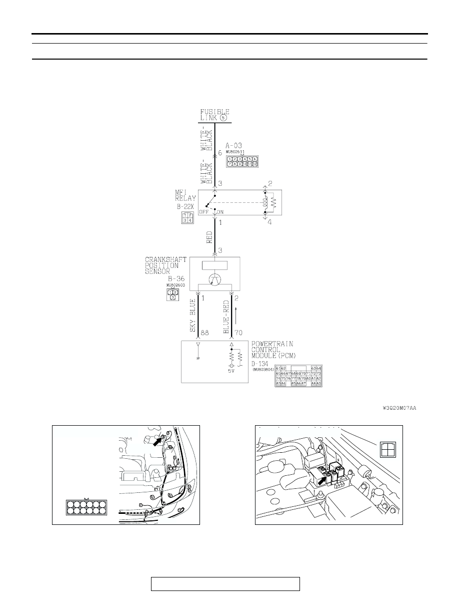
DTC 21: Crankshaft Position Sensor System

AC205188AB

Crankshaft Position Sensor System Circuit

AC204167

CONNECTOR : A-03

AT

A-03 (B)

6

12

5

3 4

2

1

9 10

8

7

11

AC204745

CONNECTOR : B-22X

AB

1
3 4

2

DIAGNOSTIC TROUBLE CODE PROCEDURES <AUTOMATIC TRANSMISSION>

TSB Revision

DIAGNOSTIC TROUBLE CODE PROCEDURES

23Ac-28

.

CIRCUIT OPERATION
The crankshaft position sensor power is supplied 
from the MFI relay (terminal 1) to the crankshaft posi-
tion sensor (terminal 3). The crankshaft position sen-
sor (terminal 1) is grounded by the PCM (terminal 
88). The PCM (terminal 70) supplies 5 volts to the 
crankshaft position sensor output (terminal 2). The 
crankshaft position sensor detects the crank angle 
(position) of each cylinder, and converts that data to 
pulse signals that are sent to the PCM.

.

DTC SET CONDITIONS
If the crankshaft position sensor does not detect an 
output pulse for more than 5 seconds while driving 
more than 25 km/h (16 mph), it is judged that there is 
an open circuit in the crankshaft position sensor and 
DTC 21 is set.

.

TROUBLESHOOTING HINTS (The most likely 
causes for this code to be set are:)

• Malfunction of the crankshaft position sensor cir-

cuit

• Damaged harness, connector

• Malfunction of the PCM

AC204168

CONNECTOR : B-36

B-36(B)

AB

2

1

3

AC204681AC

CONNECTOR: D-134

D-134 (GR)

61 62

63 64

65 66 67 68 69 70 71 72 73

82

89

81

88

80

79

78

77

87

86

85

76

75

74

84

83

DIAGNOSTIC TROUBLE CODE PROCEDURES <AUTOMATIC TRANSMISSION>

TSB Revision

DIAGNOSTIC TROUBLE CODE PROCEDURES

23Ac-29

DIAGNOSIS

Required Special Tool:

• MB991502: Scan Tool (MUT-II)

STEP 1. Using scan tool MB991502, check data list item 21: 
Crankshaft Position Sensor.

CAUTION

To prevent damage to scan tool MB991502, always turn the 
ignition switch to the "LOCK" (OFF) position before con-
necting or disconnecting scan tool MB991502.
(1) Connect scan tool MB991502 to the data link connector.
(2) With the gear selector lever in the "P" position, start the 

engine and run at idle.

(3) Set scan tool MB991502 to data reading mode for item 21, 

Crankshaft Position Sensor.

• When the accelerator pedal is not depressed (throttle 

valve is fully closed) the display on scan tool MB991502 
should be "600 to 900 r/min."

• With the accelerator pedal depressed, the engine speed 

display on scan tool MB991502 should increase accord-
ing to engine speed.

(4) Turn the ignition switch to the "LOCK" (OFF) position.
Q: Does the engine speed display increase according to 

engine speed when the accelerator pedal is depressed?
YES : 
It can be assumed that this malfunction is intermittent. 

Refer to GROUP 00, How to Use Troubleshooting/
Inspection Service Points 

− How to Cope with 

Intermittent Malfunction 

P.00-6

.

NO :  Go to Step 2.

ACX01539AD

MB991502

16-PIN

DIAGNOSTIC TROUBLE CODE PROCEDURES <AUTOMATIC TRANSMISSION>

TSB Revision

DIAGNOSTIC TROUBLE CODE PROCEDURES

23Ac-30

STEP 2. Using the oscilloscope, check the waveform at 
crankshaft position sensor connector B-36.
(1) Do not disconnect connector B-36.

(2) Connect an oscilloscope probe to crankshaft position 

sensor connector B-36 terminal 2 by backprobing.

(3) With the gear selector lever in the "P" position, start the 

engine and run at idle.

(4) Check the waveform.

• The waveform should show a pattern similar to the illus-

tration. The maximum value should be 4.8 volts or more 
and the minimum value 0.6 volt or less. The output 
waveform should not contain electrical noise.

(5) Turn the ignition switch to the "LOCK" (OFF) position.
Q: Is the waveform normal?

YES : Go to Step 3.
NO :  Go to Step 5.

AC204168

CONNECTOR : B-36

B-36(B)

AB

2

1

3

AC204946 AD

OSCILLO-
SCOPE

PROBE

B-36 HARNESS CONNECTOR : 
HARNESS SIDE

1

3

2

ACX02110AB

5V

NORMAL WAVEFORM

2 ENGINE REVOLUTIONS


Content   ..  884  885  886  887   ..