Mitsubishi Montero (2002-2004). Manual - part 875
AUTOMATIC TRANSMISSION DIAGNOSIS
TSB Revision
AUTOMATIC TRANSMISSION DIAGNOSIS
23Ab-41
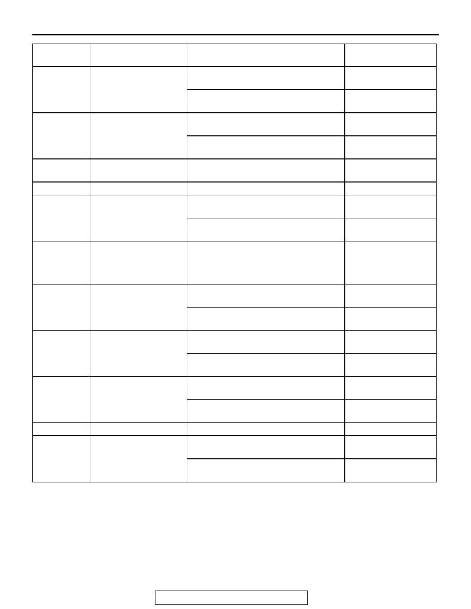
128
Low-reverse solenoid
valve
Engine: Idling
Transmission range: P
Battery positive voltage
Engine: Idling
Gear range: 2nd gear
6
− 9 V
129
Reduction solenoid
valve
Engine: Idling
Transmission range: P
Battery positive voltage
Engine: Idling
Gear range: 5th gear
6
− 9 V
130
Torque converter clutch
solenoid valve
Engine: Idling
Gear range: 1st gear
Battery positive voltage
131
Ground
Always
1 V or less
134
Shift indicator light: 3rd
Engine: Idling
Gear range: 3rd gear
Battery positive voltage
Engine: Idling
Gear range: Other than 3rd gear
1 V or less
135
Transmission fluid
temperature warning
light
Ignition switch: LOCK(OFF)
→ ON
1 V or less
→ Battery
positive voltage (after
several seconds have
elapsed)
136
Second solenoid valve
Engine: Idling
Gear range: 2nd gear
Battery positive voltage
Engine: Idling
Transmission range: P
6
− 9 V
137
Under drive solenoid
valve
Engine: Idling
Gear range: 1st gear
Battery positive voltage
Engine: Idling
Transmission range: P
6
− 9 V
138
Overdrive solenoid valve Engine: Idling
Gear range: 3rd gear
Battery positive voltage
Engine: Idling
Transmission range: P
6
− 9 V
139
Ground
Always
1 V or less
142
Shift indicator light: 4th
Engine: Idling
Gear range: 4th gear
Battery positive voltage
Engine: Idling
Gear range: Other than 4th gear
1 V or less
TERMINAL
NO.
INSPECTION ITEMS
INSPECTION REQUIREMENT
NORMAL CONDITION