Mitsubishi Montero (2002-2004). Manual - part 866


  Index      Mitsubishi     Mitsubishi Montero - service repair manual 2002-2004 year


Search            


Content   ..  864  865  866  867   ..


Mitsubishi Montero (2002-2004). Manual - part 866


AUTOMATIC TRANSMISSION DIAGNOSIS

TSB Revision

AUTOMATIC TRANSMISSION DIAGNOSIS

23Ab-5

INSPECTION USING SCAN TOOL MB991502, 
ROAD TEST AND DATA LIST

Required Special Tool:

• MB991502: Scan Tool (MUT-II)

CAUTION

To prevent damage to scan tool MB991502, always turn the 
ignition switch to the "LOCK" (OFF) position before con-
necting or disconnecting scan tool MB991502.
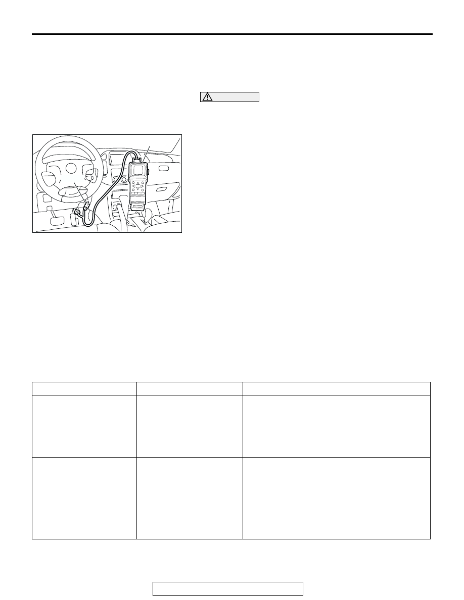
1. Connect scan tool MB991502 to data link connector.
2. Turn the ignition switch to the "ON" position.
3. Carry out the inspection by means of the Road Test and the 

Data List function. If there is an abnormality, check and 
repair the chassis harnesses and components. Refer to 

P.23Ab-7

Road Test. Refer to 

P.23Ab-33

, Data List 

Reference Table.

4. Re-check using scan tool MB991502 and confirm that the 

abnormal input and output have returned to normal because 
as a result of the repairs.

5. Check for and inspect any diagnostic trouble codes (DTCs) 

that may have surfaced from testing. Erase the diagnostic 
trouble codes after checking.

6. Turn the ignition switch to the "LOCK" (OFF) position.
7. Disconnect scan tool MB991502 from the data link 

connector.

8. Start the engine again and do a test drive to confirm that the 

problem is eliminated.

FAIL-SAFE/BACKUP FUNCTION

M1231101100106

When a malfunction of a main sensor or actuator is 
detected by the PCM, the transmission is controlled 
by pre-set control logic to maintain safe conditions 
for driving.

The following table shows how the fail-safe/backup 
function affects vehicle driveability and operation.

ACX01539AD

MB991502

16-PIN

MALFUNCTIONING ITEM JUDGMENT CONDITION

CONTROL DEFAULT DURING MALFUNCTION

Input shaft speed sensor

If no output pulse from the 
input shaft speed sensor is 
detected for one second or 
more when the vehicle 
speed is 30 km/h (19 mph) 
or greater.

The diagnostic trouble code is recorded when the 
malfunction occurs once during 4 monitoring 
periods in one drive cycle. When the judgment 
condition is met, the transmission holds 3rd gear 
or 2nd gear, depending on speed and "N" range 
light flashes as a fail-safe.

Output shaft speed sensor Output from the output 

shaft speed sensor is 
continuously 50 % or less 
of the output from the 
vehicle speed sensor one 
second or more when the 
vehicle speed is 30 km/h 
(19 mph) or more.

The diagnostic trouble code is recorded when the 
malfunction occurs once during 4 monitoring 
periods in one drive cycle. When the judgment 
condition is met, the transmission holds 3rd gear 
or 2nd gear, depending on speed and "N" range 
light flashes as a fail-safe.

AUTOMATIC TRANSMISSION DIAGNOSIS

TSB Revision

AUTOMATIC TRANSMISSION DIAGNOSIS

23Ab-6

Low-reverse solenoid 
valve

Solenoid valve resistance 
is below 2.7 ohms for 0.32 
seconds.

The diagnostic trouble code is recorded when the 
malfunction occurs during 4 monitoring periods in 
one drive cycle. When the judgment condition is 
met, the A/T control relay is turned off and "N" 
range light flashes.

Underdrive solenoid valve
Second solenoid valve
Overdrive solenoid valve
Reduction solenoid valve
Torque converter clutch 
solenoid valve
Incomplete 
shifting

1st

The gear ratio value from 
the output shaft speed 
sensor is not the same as 
the output from the input 
shaft speed sensor for one 
second after has been 
completed.

The diagnostic trouble code is recorded when the 
malfunction occurs during 4 monitoring periods in 
one drive cycle. When the judgment condition is 
met, the A/T control relay is turned off and "N" 
range light flashes.

2nd
3rd
4th
5th
Reverse

A/T control relay

A/T control relay voltage is 
less than seven volts for 
0.1 second after the ignition 
switch is turned "ON."

The A/T control relay is switched off. The 
transmission will only operate in 3rd and Reverse 
gears until the system is repaired.

Malfunction in the PCM

Malfunction has occurred in 
the PCM.

The A/T control relay is switched off. The 
transmission will only operate in 3rd and Reverse 
gears until the system is repaired.

MALFUNCTIONING ITEM JUDGMENT CONDITION

CONTROL DEFAULT DURING MALFUNCTION

AUTOMATIC TRANSMISSION DIAGNOSIS

TSB Revision

AUTOMATIC TRANSMISSION DIAGNOSIS

23Ab-7

ROAD TEST

M1231100800135

Check using the following procedures

STEP CONDITION 

BEFORE TEST/
OPERATION

TEST/
OPERATION

STANDARD

INSPECTION 
ITEM

DTC

INSPECTION 
PROCEDURE 
PAGE

1

Ignition switch: 
OFF

Ignition switch
(1) ON

Data list No. 54

(1) Control Relay 

Voltage [V]

A/T Control 
relay output 
voltage

54

A/T Control 
relay system 
(

P.23Ac-237

)

2

Ignition switch: 
ON
Engine: Stopped
Transmission 
range: P

Transmission 
range
(1) P, (2) R, (3) 
N, (4) D

Data list No. 61
(1) P, (2) R, (3) N, 
(4) D

Transmission 
range switch

27, 28

Transmission 
range switch 
system 
(

P.23Ac-93

 , 

P.23Ac-123

)

Transmission 
range
(1) D (1st gear)
(2) Select the 
sport mode (1st 
gear)
(3) Upshift and 
hold the selector 
lever in that 
position (2nd 
gear)
(4) Downshift 
and hold the 
selector lever in 
that position (1st 
gear)

Data list No. 67
(1) OFF, (2) ON, 
(3) ON, (4) ON
Data list No. 68
(1) OFF, (2) OFF, 
(3) ON, (4) OFF
Data list No. 69
(1) OFF, (2) OFF, 
(3) OFF, (4) ON

Select switch
Shift switch

-

Shift switch 
assembly 
system 
(

P.23Ad-48

)

Shift indicator light
(1) "D" and "1" 
illuminates
(2) Only "1" 
illuminates
(3) Only "2" 
illuminates
(4) Only "1" 
illuminates

Accelerator 
pedal
(1) Fully closed
(2) Depressed
(3) Fully open

Data list No. 11
(1) 200 

− 800 mV

(2) Gradually rises 
from (1)
(3) 3,800 

− 4,900 

mV

Throttle 
position sensor

Brake pedal
(1) Depressed
(2) Released

Data list No. 26
(1) ON
(2) OFF

Stoplight 
switch

26

Stoplight switch 
system 
(

P.23Ac-83

)

Transfer position
(1) Other than 
4LLc
(2) 4LLc

Data list No. 26
(1) OFF
(2) ON

4LLc detection 
switch

4LLc detection 
switch system 
(

P.23Ad-67

)

3

Ignition switch: 
ST
Engine: Stopped

Cranking test 
with lever in P or 
N range

Cranking should 
be possible

Cranking

Engine does not 
start (

P.23Ad-2

)

AUTOMATIC TRANSMISSION DIAGNOSIS

TSB Revision

AUTOMATIC TRANSMISSION DIAGNOSIS

23Ab-8

4

Engine warmed

Drive for 15 
minutes or more 
so that the 
transmission 
fluid temperature 
becomes 70 

− 

80

°C. (158 − 

176

°F)

Data list No. 15
Gradually rises to 
70 

− 80°C (158 − 

176

°F)

Transmission 
fluid 
temperature 
sensor

15, 16

Transmission 
fluid 
temperature 
sensor system 
(

P.23Ac-2

P.23Ac-18

)

STEP CONDITION 

BEFORE TEST/
OPERATION

TEST/
OPERATION

STANDARD

INSPECTION 
ITEM

DTC

INSPECTION 
PROCEDURE 
PAGE


Content   ..  864  865  866  867   ..