Mitsubishi Montero (2002-2004). Manual - part 829


  Index      Mitsubishi     Mitsubishi Montero - service repair manual 2002-2004 year


Search            


Content   ..  827  828  829  830   ..


Mitsubishi Montero (2002-2004). Manual - part 829


CAMSHAFT OIL SEAL

TSB Revision

ENGINE MECHANICAL

11A-21

REMOVAL SERVICE POINTS

.

<<A>> CAMSHAFT SPROCKET REMOVAL
Use special tools MD998715 and MB990767 to remove the 
camshaft sprocket.

.

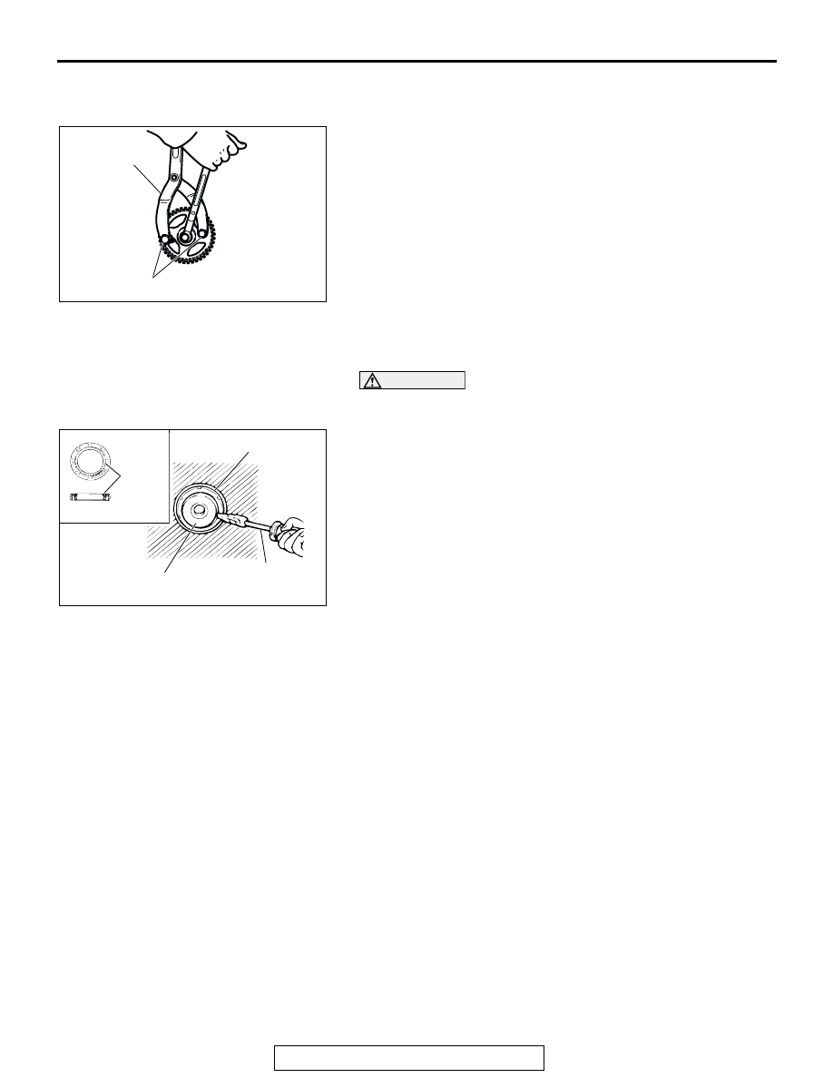
<<B>> CAMSHAFT OIL SEAL REMOVAL
1. Make a notch in the oil seal lip section with a knife, etc.

CAUTION

Be careful not to damage the camshaft and the cylinder 
head.
2. Cover the end of a flat-tipped screwdriver with a shop towel 

and insert into the notched section of the oil seal, and pry 
out the oil seal to remove it.

ACX00301AB

MB990767

MD998715

ACX00373AB

FLAT-TIPPED
SCREWDRIVER

CAMSHAFT

OIL SEAL

LIP 
SECTION

CAMSHAFT OIL SEAL

TSB Revision

ENGINE MECHANICAL

11A-22

INSTALLATION SERVICE POINTS

.

>>A<< CAMSHAFT OIL SEAL INSTALLATION
1. Apply engine oil to the camshaft oil seal lip.
2. Use special tools MD998713 and MB991559 to press-fit the 

camshaft oil seal.

.

>>B<< CAMSHAFT SPROCKET INSTALLATION
Use special tools MD998715 and MB990767 in the same way 
as during removal to install the camshaft sprocket.

ACX00371AB

MB991559

MD998713

<LEFT BANK>

ACX00372 AB

MD998713

<RIGHT BANK>

OIL PAN AND OIL SCREEN

TSB Revision

ENGINE MECHANICAL

11A-23

OIL PAN AND OIL SCREEN

REMOVAL AND INSTALLATION

M1112002500160

Pre-removal and Post-installation Operation
• Skid Plate and Under Cover Removal and Installation

• Engine Oil Draining and Refilling (Refer to GROUP 12, 

On-vehicle Service 

P.12-3

.)

• Starter Motor Removal and Installation (Refer to GROUP 

16, Starter motor assembly 

P.16-20

.)

AC204078

7

FLUID :
  DIAMOND ATF SP II M OR SP III

9

ENGINE OIL

N

N

N

7

44 ± 8 N·m
33 ± 5 ft-lb

24 ± 4 N·m
18 ± 3 ft-lb

14 ± 1 N·m
120 ± 13 in-lb

9

19 ± 3 N·m
14 ± 2 ft-lb

13

12

9.0 ± 1.0 N·m
80 ± 9 in-lb

8.5 ± 3.5 N·m
75 ± 31 in-lb

6

8.5 ± 3.5 N·m
75 ± 31 in-lb

8.5 ± 3.5 N·m
75 ± 31 in-lb

11 ± 0.5 N·m
93 ± 4 in-lb

37 ± 7 N·m
27 ± 5 ft-lb

11

5

60 ± 10 N·m
45 ± 7 ft-lb

4

37 ± 7 N·m
27 ± 5 ft-lb

39 ± 5 N·m
29 ± 3 ft-lb

60 ± 10 N·m
45 ± 7 ft-lb

69 ± 9 N·m
51 ± 7 ft-lb

1

2

3

N

AB

10

8

10

REMOVAL STEPS

1.

DRIVE SHAFT (RH) 
CONNECTION

2.

DRIVE SHAFT (LH) 
CONNECTION

3.

FRONT DIFFERENTIAL NUMBER 
2 CROSSMEMBER ASSEMBLY

4.

DRAIN PLUG

5.

DRAIN PLUG GASKET

6.

COVER

7.

TRANSMISSION FLUID DIPSTICK 
ASSEMBLY

8.

O-RING

9.

ENGINE OIL DIPSTICK 
ASSEMBLY

10. O-RING

<<A>>

>>A<<

11. OIL PAN
12. OIL SCREEN
13. GASKET

REMOVAL STEPS (Continued)

OIL PAN AND OIL SCREEN

TSB Revision

ENGINE MECHANICAL

11A-24

REMOVAL SERVICE POINT

.

<<A>> OIL PAN REMOVAL
1. Remove the oil pan mounting bolts.

CAUTION

Do not use the oil pan remover (MD998727). It will damage 
the oil pan (aluminum made).
2. Screw the bolts (M10) securing the oil pan to the 

transmission assembly in the illustrated bolt holes, then 
remove the oil pan.

INSTALLATION SERVICE POINTS

.

>>A<< OIL PAN INSTALLATION
1. Remove sealant from the oil pan and cylinder block mating 

surfaces.

2. Degrease the sealant-coated surface and the engine mating 

surface.

3. Apply a bead of the sealant to the cylinder block mating 

surface of the engine oil pan as shown.

Specified sealant: MITSUBISHI GENUINE PART 
MD970389 or equivalent

NOTE: The sealant should be applied in a continuous bead 
approximately 4.0 mm (0.16 inch) in diameter.

4. Assemble the oil pan to the cylinder block within 30 minutes 

after applying the sealant.

CAUTION

The bolt holes for bolts 13 and 14 in the illustration are cut 
away on the transmission side. Be careful not to insert 
these bolts at an angle.
5. Tighten the bolts in order of the numbers shown in the 

illustration.

ACX00753AB

ACX00754AB

1

2

3

4

5

6

7

8

9

10

11

12

13

14

15

16

CYLINDER BLOCK

REAR OIL SEAL CASE

OIL PAN

TRANSMISSION 
SIDE

(MOUNTING BOLT)

13,14

BOLT HOLE

GROOVE

Ø 4.0 mm
(0.16 in)


Content   ..  827  828  829  830   ..