Mitsubishi Montero (2002-2004). Manual - part 817
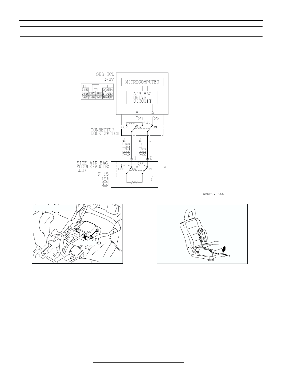
SRS AIR BAG DIAGNOSIS
TSB Revision
SUPPLEMENTAL RESTRAINT SYSTEM (SRS) DIAGNOSIS
52Bb-137
DTC 82:Left Hand Side-Airbag Module (Squib) System Fault 2 (Open in the Squib Circuit)
.
CIRCUIT OPERATION
• The SRS-ECU judges how severe a collision is
by detecting signals from the left and right side
impact sensors. If the impact is over a predeter-
mined level, the SRS-ECU outputs an ignition
signal. At this time, if the side-airbag safing G-
sensor is on, the SRS side-airbag will inflate.
• The ignition signal is input to the side-airbag
module to inflate the side-airbag.
.
DTC SET CONDITIONS
This DTC is set if there is abnormal resistance
between the input terminals of the side-airbag mod-
ule (LH) (squib).
.
TROUBLESHOOTING HINTS
• Open circuit in the left hand side-airbag module
(squib) circuit
• Improper connector contact
• Malfunction of the SRS-ECU
.
AC204439AB
NOTE
: CONNECTOR LOCK SWITCH
CONNECTOR
CONNECTED: ON
CONNECTOR
DISCONNECTED: OFF
Side-Airbag Module (LH) (Squib) Circuit
ACX01478AI
CONNECTOR: E-07
E-07 (Y)
AC204635 AB
CONNECTOR: F-15
F-15 (R)