Mitsubishi Montero (2002-2004). Manual - part 804


  Index      Mitsubishi     Mitsubishi Montero - service repair manual 2002-2004 year


Search            


Content   ..  802  803  804  805   ..


Mitsubishi Montero (2002-2004). Manual - part 804


SRS AIR BAG DIAGNOSIS

TSB Revision

SUPPLEMENTAL RESTRAINT SYSTEM (SRS) DIAGNOSIS

52Bb-85

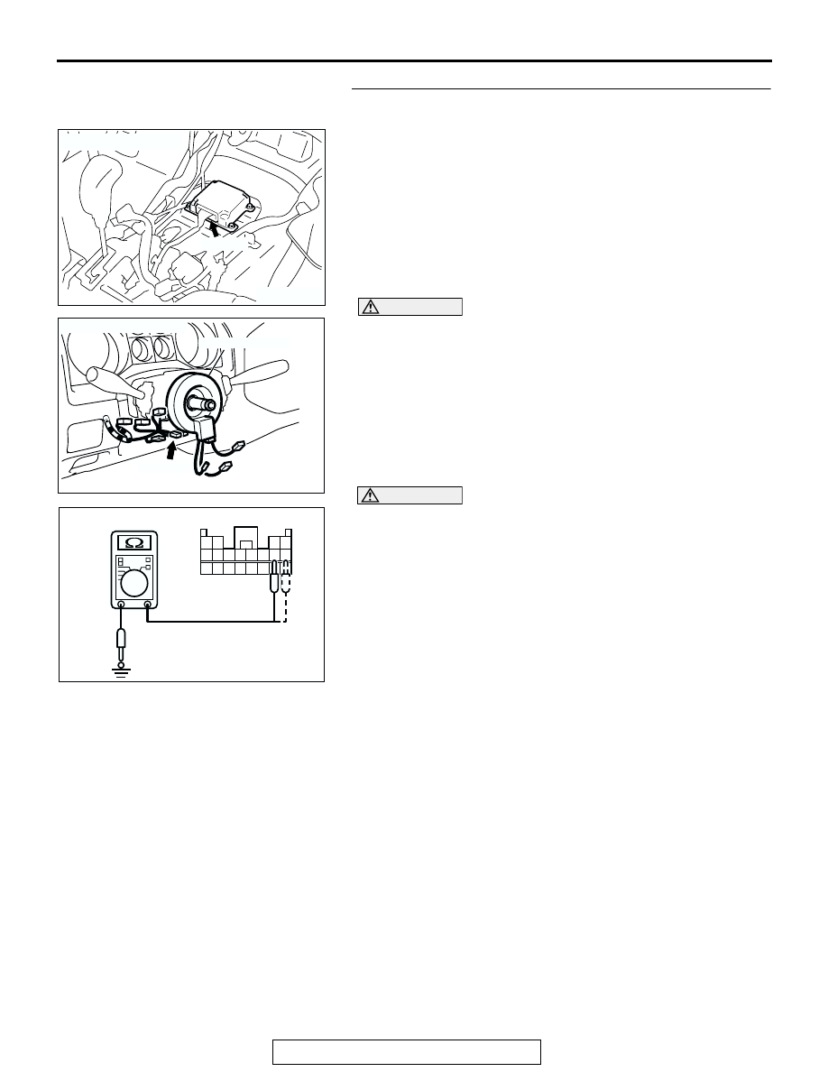
STEP 3. Check the harness for short circuit to ground 
between the SRS-ECU and the clock spring.
(1) Disconnect SRS-ECU connector E-08.

DANGER

To prevents the air bag from deploying unintention-
ally, disconnect the clock spring connector D-206 to 
short the squib circuit.

(2) Disconnect the clock spring connector D-206.

CAUTION

Do not insert a test probe into the terminal from its front 
side directly as the connector contact pressure may be 
weakened.
(3) Check for continuity between E-08 harness connector 

terminals 11, 12 and body ground.
It should be open circuit.

Q: Does continuity exist? 

YES : Erase the diagnostic trouble code memory, and check 

the diagnostic trouble code. If DTC 62 sets, replace 
the SRS-ECU. (Refer to 

P.52Ba-31

.) Then go to Step 

5.

NO :  Go to Step 4. 

ACX01478 AG

CONNECTOR: E-08

E-08 (Y)

AC204226AB

CONNECTOR: D-206

CLOCK SPRING

D-206 (Y)

AC006256

13 14 15 16 17 18 19 20

5 6 7 8 9 10 11 12

1 2

3 4

E-08 HARNESS CONNECTOR: HARNESS SIDE

AJ

SRS AIR BAG DIAGNOSIS

TSB Revision

SUPPLEMENTAL RESTRAINT SYSTEM (SRS) DIAGNOSIS

52Bb-86

STEP 4. Check the harness for short circuit to ground 
between SRS-ECU connector E-08 (terminal No.11 and 12) 
and clock spring connector D-206 (terminal No.3 and 4).
Q: Are the harness wires between SRS-ECU connector E-

08 (terminal No.11 and 12) and clock spring connector 
D-206 (terminal No.3 and 4) in good condition?
YES : 
Go to Step 5.
NO :  Repair the harness wires between SRS-ECU 

connector E-08 and clock spring connector D-206. 
Then go to Step 5.

STEP 5. Recheck for diagnostic trouble code. 
Q: Is DTC 62 set?

YES : Return to Step 1.
NO :  The procedure is complete. (If no malfunctions are not 

found in all steps, an intermittent malfunction is 
suspected. Refer to GROUP 00, How to Use 
Troubleshooting/Inspection Service Points 

− How to 

Cope with Intermittent Malfunction 

P.00-6

.) 

ACX01478AH

CONNECTOR: E-08

E-08 (Y)

HARNESS
CONNECTOR:
HARNESS SIDE

AC204226AC

CONNECTOR: D-206

CLOCK SPRING

D-206 (Y)

HARNESS 
CONNECTOR:
HARNESS SIDE

1 2

4

3

SRS AIR BAG DIAGNOSIS

TSB Revision

SUPPLEMENTAL RESTRAINT SYSTEM (SRS) DIAGNOSIS

52Bb-87

DTC 64: Passenger’s (Front) Air Bag Module (Squib) System Fault for Power Supply Circuit (Short-
Circuited to Power Supply)

.

CIRCUIT OPERATION

• The SRS-ECU judges how severe a collision is 

by detecting signals from the front impact sensors 
and the front air bag analog G-sensor. If the 
impact is over a predetermined level, the SRS-
ECU outputs an ignition signal. At this time, if the 
front air bag safing G-sensor is on, the SRS air 
bag will inflate. 

• The ignition signal is input to the air bag module 

via the clock spring to inflate the air bag.

.

DTC SET CONDITIONS
This DTC is set if there is abnormal resistance 
between the input terminals of the passenger's air 
bag module (squib). However, if no DTC resets, the 
SRS warning light will be switched off (DTC will be 
retained). 

.

TROUBLESHOOTING HINTS

• Damaged harness wires and connectors

• Short to the power supply in the passenger's air 

bag module (squib) harness

• Malfunction of the SRS-ECU

.

AC204435AB

Passenger's (Front) Air Bag Module (Squib) Circuit

NOTE

: CONNECTOR LOCK SWITCH

CONNECTOR

CONNECTED: ON
CONNECTOR

DISCONNECTED: OFF

AC204125

CONNECTOR: D-11

AC

D-11 (R)

GLOVE BOX
STRIKER

ACX01478 AG

CONNECTOR: E-08

E-08 (Y)

SRS AIR BAG DIAGNOSIS

TSB Revision

SUPPLEMENTAL RESTRAINT SYSTEM (SRS) DIAGNOSIS

52Bb-88

DIAGNOSIS

Required Special Tools:

• MB991502: Scan Tool (MUT-II)

• MB991865: Dummy resister

• MB991866: Resister harness

STEP1. Check the passenger's air bag module (squib).
(1) Disconnect the negative battery terminal.
(2) Unclip passenger’s air bag module connector D-11.

(3) Connect special tool MB991865 to special tool MB991866.

CAUTION

Do not insert a test probe into the terminal from its front 
side directly as the connector contact pressure may be 
weakened.
(4) Disconnect the passenger's air bag module connector D-11, 

and insert special tool MB991866 into the harness 
connector by backprobing.

(5) Connect the negative battery terminal.
(6) Erase the diagnostic trouble code memory, and check the 

diagnostic trouble code.

Q:  Is DTC 64 set?

YES : Go to Step 2.
NO :  Replace the passenger's air bag module. (Refer to 

P.52Ba-33

.) Then go to Step 4. 

AC204125

CONNECTOR: D-11

AC

D-11 (R)

GLOVE BOX
STRIKER

AC006042 AV

MB991865 (DUMMY 
RESISTOR: 3 

)

MB991866
(RESISTOR HARNESS)

D-11 HARNESS 
CONNECTOR

D-11 PASSENGER'S AIR BAG 
MODULE CONNECTOR


Content   ..  802  803  804  805   ..