Mitsubishi Montero (2002-2004). Manual - part 796


  Index      Mitsubishi     Mitsubishi Montero - service repair manual 2002-2004 year


Search            


Content   ..  794  795  796  797   ..


Mitsubishi Montero (2002-2004). Manual - part 796


SRS AIR BAG DIAGNOSIS

TSB Revision

SUPPLEMENTAL RESTRAINT SYSTEM (SRS) DIAGNOSIS

52Bb-53

DTC SET CONDITIONS
This DTC is set if the voltage between the IG1 termi-
nals (fuse No.6 circuit) and ground is lower than a 
predetermined value for a continuous period of five 
second or more. However, if the vehicle condition 
returns to normal, DTC number 41 will be automati-
cally erased, and the SRS warning light will switch 
off.

.

TROUBLESHOOTING HINTS

• Damaged wiring harnesses or connectors

• Malfunction of the SRS-ECU

.

DIAGNOSIS

Required Special Tools:

• MB991502: Scan Tool (MUT-ll)

• MB991223 (MB991222): Harness set (Probe)

STEP 1. Check junction block fuse number 6.
Q: Is the fuse burned out?

NO :  Go to Step 2.
YES : Go to Step 4.

STEP 2. Check the circuit between the SRS-ECU and the 
ignition switch (IG1).
(1) Disconnect the negative battery terminal.
(2) Disconnect SRS-ECU connector E-08.
(3) Connect the negative battery terminal.
(4) Turn the ignition switch to the "ON" position.

CAUTION

Do not insert a test probe into the terminal from its front 
side directly as the connector contact pressure may be 
weakened.
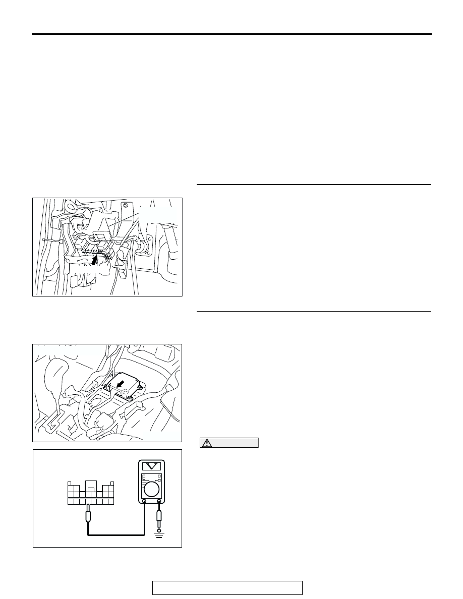
(5) Measure the Voltage between E-08 harness connector 

terminal 16 and body ground.
Voltage should measure 9 volts or more.

Q: Is the measured voltage within the specified range?

YES : Erase the diagnostic trouble code memory, and check 

the diagnostic trouble code. If DTC 41 sets, replace 
the SRS-ECU. (Refer to 

P.52Ba-31

.) Then go to Step 

10.

NO :  Go to Step 3.

AC203896AC

JUNCTION
BLOCK

FUSE No.6

ACX01478 AD

CONNECTOR: E-08

13 14 15 16 17 18 19 20

5 6 7 8 9 10 11 12

1 2

3 4

AC203786AC

E-08 HARNESS 
CONNECTOR:
HARNESS SIDE

SRS AIR BAG DIAGNOSIS

TSB Revision

SUPPLEMENTAL RESTRAINT SYSTEM (SRS) DIAGNOSIS

52Bb-54

STEP 3. Check the harness for open circuit between SRS-
ECU connector E-08 (terminal No.16) and the ignition 
switch connector D-204 (terminal No.2).
NOTE: After inspecting junction block connectors D-210 and D-
208, inspect the wiring harness. If junction block connectors 
are damaged, repair or replace them. (Refer to GROUP 00E, 
Harness Connector Inspection 

P.00E-2

.) Then go to Step 10.

Q: Are harness between SRS-ECU connector E-08 

(terminal No.16) and the ignition switch connector D-
204 (terminal No.2) in good condition?
YES : 
Go to Step 10.
NO :  Repair the harness wire between SRS-ECU 

connector E-08 and the ignition switch connector D-
204. Then go to Step 10.

AC204257

CONNECTORS : D-208, D-210

AB

D-210

D-208

D-208 HARNESS CONNECTOR:
COMPONENT SIDE

D-210 HARNESS CONNECTOR:
COMPONENT SIDE

1

2

3

5

6

4

JUNCTION BLOCK
(FRONT VIEW)

5 4

3 2

12

13

10

11

7

8

1

6

9

ACX01478AH

CONNECTOR: E-08

E-08 (Y)

HARNESS
CONNECTOR:
HARNESS SIDE

AC204226AE

CLOCK SPRING

CONNECTOR: D-204

D-204

HARNESS 
CONNECTOR:
COMPONENT 
SIDE

2
5

6

3

4

1

SRS AIR BAG DIAGNOSIS

TSB Revision

SUPPLEMENTAL RESTRAINT SYSTEM (SRS) DIAGNOSIS

52Bb-55

STEP 4. Check a burned-out fuse.
(1) Replace the fuse.
(2) Turn the ignition switch to the "ON" position, wait for at least 

one minute and then turn the ignition switch to the "LOCK" 
(OFF) position. 

(3) Check the fuse.
Q: Is the fuse in good condition?

YES : Then go to Step 10.
NO :  Go to Step 5.

STEP 5. Check the harness for short circuit to ground 
between the SRS-ECU and the junction block.
(1) Disconnect junction block connector D-210, and measure at 

the wiring harness.

CAUTION

Do not insert a test probe into the terminal from its front 
side directly as the connector contact pressure may be 
weakened.
(2) Check for continuity between D-210 harness connector 

terminal 2 and body ground.
It should be open circuit.

Q: Does continuity exist?

YES : Go to Step 6.
NO :  Go to Step 8.

ACX01632

CONNECTOR: D-210

JUNCTION BLOCK
(FRONT VIEW)

AH

D-210

AC204259

1 2 3

4

12

9

8

7

6

10

5

13

11

AB

D-210 HARNESS 
CONNECTOR: 
HARNESS SIDE

SRS AIR BAG DIAGNOSIS

TSB Revision

SUPPLEMENTAL RESTRAINT SYSTEM (SRS) DIAGNOSIS

52Bb-56

STEP 6. Check the fuse number 6-related circuit at 
junction block connector C-205.
(1) Disconnect junction block connector D-210, and measure at 

the wiring harness.

CAUTION

Do not insert a test probe into the terminal from its front 
side directly as the connector contact pressure may be 
weakened.
(2) Check for continuity between D-210 harness connector 

terminal 1 and body ground.
It should be open circuit.

Q: Does continuity exist?

YES : Check the other circuit, which flows through multi-

purpose fuse number 6.

NO :  Go to Step 7.

ACX01632

CONNECTOR: D-210

JUNCTION BLOCK
(FRONT VIEW)

AH

D-210

AC204260

1 2 3

4

12

9

8

7

6

10

5

13

11

AB

D-210 HARNESS 
CONNECTOR: 
HARNESS SIDE


Content   ..  794  795  796  797   ..