Mitsubishi Montero (2002-2004). Manual - part 747


  Index      Mitsubishi     Mitsubishi Montero - service repair manual 2002-2004 year


Search            


Content   ..  745  746  747  748   ..


Mitsubishi Montero (2002-2004). Manual - part 747


TSB Revision

SYMPTOM PROCEDURES

13Ad-37

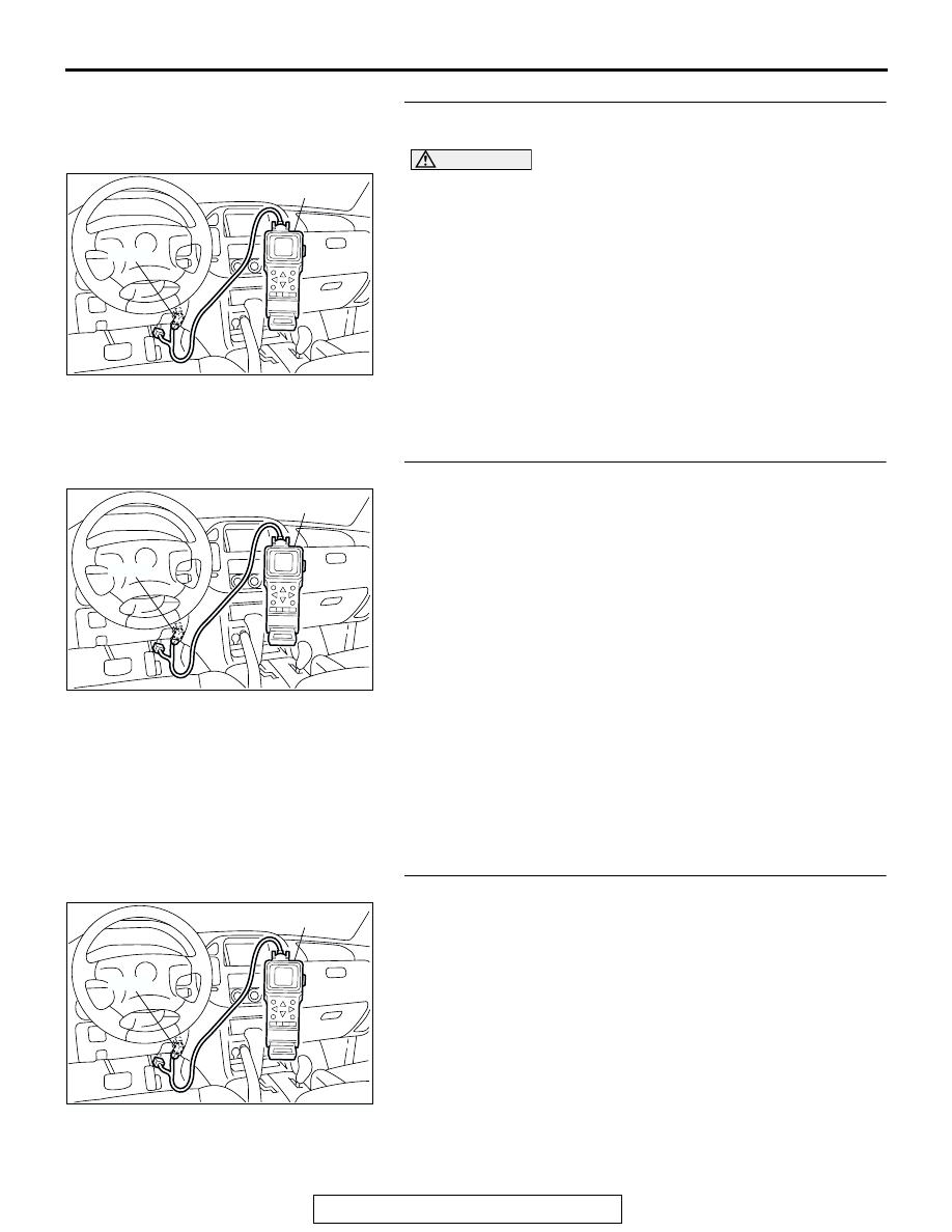
STEP 5. Using scan tool MB991502, check actuator test 
items 01, 02, 03, 04, 05, 06: Injector.

CAUTION

To prevent damage to scan tool MB991502, always turn the 
ignition switch to the "LOCK" (OFF) position before con-
necting or disconnecting scan tool MB991502.
(1) Connect scan tool MB991502 to the data link connector.
(2) Turn the ignition switch to the "ON" position.
(3) Check following items in the actuator test. Refer to GROUP 

13A, Actuator Test Reference Table 

P.13Ab-42

.

a. Item 01, 02, 03, 04, 05, 06: Injector.

(4) Turn the ignition switch to the "LOCK" (OFF) position.
Q: Is the actuator operating properly?

YES : Go to Step 6.
NO :  Refer to GROUP 13A, DTC P0201, P0202, P0203, 

P0204, P0205, P0206 

− Injector Circuit 

P.13Ac-318

.

STEP 6. Using scan tool MB991502, check data list.
(1) Turn the ignition switch to the "ON" position.
(2) Check the following items in the data list. Refer to GROUP 

13A, Data List Reference Table 

P.13Ab-29

.

a. Item 13: Intake Air Temperature Sensor.
b. Item 25: Barometric Pressure Sensor.

c. Item 21: Engine Coolant Temperature Sensor.

d. Item 69: Right Bank Heated Oxygen Sensor (rear).
e. Item 39: Right Bank Heated Oxygen Sensor (front).

f. Item 59: Left Bank Heated Oxygen Sensor (rear).

g. Item 11: Left Bank Heated Oxygen Sensor (front).
h. Item 27: Power Steering Pressure Switch.

i. Item 28: A/C Switch.

(3) Turn the ignition switch to the "LOCK" (OFF) position.
Q: Are they operating properly?

YES : Go to Step 7.
NO :  Repair or replace. Then confirm that the malfunction 

symptom is eliminated.

STEP 7. Using scan tool MB991502, check actuator test.
(1) Turn the ignition switch to the "ON" position.
(2) Check the following items in the actuator test. Refer to 

GROUP 13A, Actuator Test Reference Table 

P.13Ab-42

.

a. Item 08: Evaporative Emission Purge Solenoid.

(3) Turn the ignition switch to the "LOCK" (OFF) position.
Q: Is the actuator operating properly?

YES : Go to Step 8.
NO :  Repair or replace. Then confirm that the malfunction 

symptom is eliminated.

ACX01539

16-PIN

MB991502

AC

ACX01539

16-PIN

MB991502

AC

ACX01539

16-PIN

MB991502

AC

TSB Revision

SYMPTOM PROCEDURES

13Ad-38

STEP 8. Check the fuel pressure.
Refer to GROUP 13A, On-vehicle Service 

− Fuel Pressure Test 

P.13Aa-13

.

Q: Is the fuel pressure normal?

YES :  a. Check the following items, and repair or replace 

the defective items.

• Vacuum leak.

• Broken intake manifold gasket.

• Broken air intake hose.

• Broken vacuum hose.

• Positive crankcase ventilation valve does not 

operate.

b. Injector clogged.

Then confirm that the malfunction symptom is 
eliminated.

NO :  Repair or replace. Then confirm that the malfunction 

symptom is eliminated.

STEP 9. Check the ignition timing.
Refer to GROUP 11A, On-vehicle Service 

− Ignition Timing 

Check 

P.11A-6

.

Q: Is the ignition timing normal?

YES : Check the following items, and repair or replace the 

defective items.

a. Check the ignition coil, spark plugs, spark plug 

cables.

b. Check the purge control system.

c. Check compression pressure.

d. Check if the foreign materials (water, 

kerosene, etc.) got into fuel.

e. Check the EGR valve.

Then confirm that the malfunction symptom is 

eliminated.

NO :  Check that the crankshaft position sensor and timing 

belt cover are in the correct position. Then confirm 
that the malfunction symptom is eliminated.

TSB Revision

SYMPTOM PROCEDURES

13Ad-39

INSPECTION PROCEDURE 9: Idle speed is high (improper idle speed).

.

COMMENT

• In such cases as the above, the cause is proba-

bly that the intake air volume during idle is too 
great.

.

TROUBLESHOOTING HINTS (The most likely 
causes for this case: )

• Malfunction of the electronic control throttle valve 

system.

• Malfunction of the throttle body.

DIAGNOSIS

Required Special Tool:

• MB991502: Scan Tool (MUT-II)

STEP 1. Using scan tool MB991502, read the diagnostic 
trouble code (DTC).

CAUTION

To prevent damage to scan tool MB991502, always turn the 
ignition switch to the "LOCK" (OFF) position before con-
necting or disconnecting scan tool MB991502.
(1) Connect scan tool MB991502 to the data link connector.
(2) Turn the ignition switch to the "ON" position.
(3) Read the DTC.
(4) Turn the ignition switch to the "LOCK" (OFF) position.
Q: Is DTC set?

YES : Refer to GROUP 13A, Diagnostic Trouble Code Chart 

P.13Ab-22

.

NO :  Go to Step 2.

STEP 2. Using scan tool MB991502, check data list.

CAUTION

To prevent damage to scan tool MB991502, always turn the 
ignition switch to the "LOCK" (OFF) position before con-
necting or disconnecting scan tool MB991502.
(1) Connect scan tool MB991502 to the data link connector.
(2) Turn the ignition switch to the "ON" position.
(3) Check the following items in the data list. Refer to GROUP 

13A, Data List Reference Table 

P.13Ab-29

.

a. Item 21: Engine Coolant Temperature Sensor.
b. Item 28: A/C Switch.

(4) Turn the ignition switch to the "LOCK" (OFF) position.
Q: Are they operating properly?

YES : Go to Step 3.
NO :  Repair or replace. Then confirm that the malfunction 

symptom is eliminated.

ACX01539

16-PIN

MB991502

AC

ACX01539

16-PIN

MB991502

AC

TSB Revision

SYMPTOM PROCEDURES

13Ad-40

STEP 3. Using scan tool MB991502, check actuator test.
(1) Turn the ignition switch to the "ON" position.
(2) Check the following items in the actuator test. Refer to 

GROUP 13A, Actuator Test Reference Table 

P.13Ab-42

.

a. Item 08: Evaporative Emission Purge Solenoid.

(3) Turn the ignition switch to the "LOCK" (OFF) position.
Q: Is the actuator operating properly?

YES : Refer to GROUP 13A, On-vehicle Service 

− Clean the 

throttle valve area 

P.13Aa-11

.

NO :  Repair or replace. Then confirm that the malfunction 

symptom is eliminated.

INSPECTION PROCEDURE 10: Idle Speed Is Low (Improper Idle Speed).

.

COMMENT

• In cases such as the above, the cause is proba-

bly that the intake air volume during idle is too 
small.

.

TROUBLESHOOTING HINTS (The most likely 
causes for this case: )

• Malfunction of the electronic control throttle valve 

system.

• Malfunction of the throttle body.

DIAGNOSIS

Required Special Tool:

• MB991502: Scan Tool (MUT-II)

STEP 1. Using scan tool MB991502, read the diagnostic 
trouble code (DTC).

CAUTION

To prevent damage to scan tool MB991502, always turn the 
ignition switch to the "LOCK" (OFF) position before con-
necting or disconnecting scan tool MB991502.
(1) Connect scan tool MB991502 to the data link connector.
(2) Turn the ignition switch to the "ON" position.
(3) Read the DTC.
(4) Turn the ignition switch to the "LOCK" (OFF) position.
Q: Is DTC set?

YES : Refer to GROUP 13A, Diagnostic Trouble Code Chart 

P.13Ab-22

.

NO :  Go to Step 2.

ACX01539

16-PIN

MB991502

AC

ACX01539

16-PIN

MB991502

AC


Content   ..  745  746  747  748   ..