Mitsubishi Montero (2002-2004). Manual - part 745


  Index      Mitsubishi     Mitsubishi Montero - service repair manual 2002-2004 year


Search            


Content   ..  743  744  745  746   ..


Mitsubishi Montero (2002-2004). Manual - part 745


TSB Revision

SYMPTOM PROCEDURES

13Ad-29

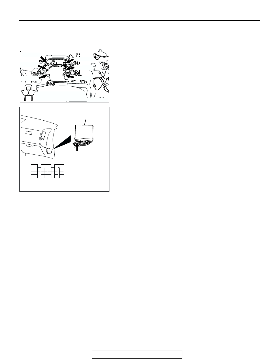
STEP 14. Check for harness damage between injector 
connector and PCM connector.

a. Check the harness wire between injector connector B-

01 (terminal No. 2) and PCM connector D-132 (terminal 
No. 1) when checking No. 1 cylinder injector.

b. Check the harness wire between injector connector B-

33 (terminal No. 2) and PCM connector D-132 (terminal 
No. 5) when checking No. 2 cylinder injector.

c. Check the harness wire between injector connector B-

02 (terminal No. 2) and PCM connector D-132 (terminal 
No. 14) when checking No. 3 cylinder injector.

d. Check the harness wire between injector connector B-

35 (terminal No. 2) and PCM connector D-132 (terminal 
No. 21) when checking No. 4 cylinder injector.

e. Check the harness wire between injector connector B-

03 (terminal No. 2) and PCM connector D-132 (terminal 
No. 2) when checking No. 5 cylinder injector.

f. Check the harness wire between injector connector B-

11 (terminal No. 2) and PCM connector D-132 (terminal 
No. 6) when checking No. 6 cylinder injector.

Q: Is the harness wire in good condition?

YES : Check the following items, and repair or replace the 

defective items.

a. Check the ignition coil, spark plugs, spark plug 

cables.

b. Check if the injectors are clogged.

c. Check compression pressure.

d. Check fuel lines for clogging.
e. Check if the foreign materials (water, 

kerosene, etc.) got into fuel.

f. Check the EGR valve.

Then confirm that the malfunction symptom is 

eliminated.

NO :  Repair it. Then confirm that the malfunction symptom 

is eliminated.

AK200960

1

2

B-03(GR)

B-11(GR)

B-35(GR)

B-33(GR)

B-02(GR)

B-01(GR)

CONNECTORS: B-01, B-02, B-03, B-11, 

B-33, B-35

AB

HARNESS CONNECTOR: 
COMPONENT SIDE

AK200938

2

3

4

5

6

7

8

9

1

10

14

15

16

17

18

19

20

21

22

23

24

25

26

27

11

12

13

AB

CONNECTOR: D-132

HARNESS CONNECTOR: 
COMPONENT SIDE

PCM

D-132(GR)

TSB Revision

SYMPTOM PROCEDURES

13Ad-30

INSPECTION PROCEDURE 7: Hard Starting

.

COMMENT

• In cases such as the above, the cause is usually 

either weak spark, improper air-fuel mixture or 
low compression.

.

TROUBLESHOOTING HINTS (The most likely 
causes for this case: )

• Malfunction of the ignition system.

• Malfunction of the injector system.

• Poor fuel quality. (Contamination)

• Poor compression.

• Dirtiness around throttle valve.

• Malfunction of the EGR valve.

DIAGNOSIS

Required Special Tool:

• MB991502: Scan Tool (MUT-II)

STEP 1. Check the battery positive voltage.
(1) Measure the battery positive voltage during cranking.

• The voltage is 8 volts or more.

Q: Dose the voltage remain greater than 8 volts while the 

engine is cranked?
YES : 
Go to Step 2.
NO :  Refer to GROUP 54A, Battery 

− Battery chec

P.54A-

4

.

STEP 2. Using scan tool MB991502, read the diagnostic 
trouble code (DTC).

CAUTION

To prevent damage to scan tool MB991502, always turn the 
ignition switch to the "LOCK" (OFF) position before con-
necting or disconnecting scan tool MB991502.
(1) Connect scan tool MB991502 to the data link connector.
(2) Turn the ignition switch to the "ON" position.
(3) Read the DTC.
(4) Turn the ignition switch the "LOCK" (OFF) position.
Q: Is DTC set?

YES : Refer to GROUP 13A, Diagnostic Trouble Code Chart 

P.13Ab-22

NO :  Go to Step 3.

STEP 3. Using scan tool MB991502, check actuator test.
(1) Turn the ignition switch to the "ON" position.
(2) Check the following items in the actuator test. Refer to 

GROUP 13A, Actuator Test Reference Table 

P.13Ab-42

.

a. Item 07: Fuel Pump.

(3) Turn the ignition switch to the "LOCK" (OFF) position.
Q: Is the actuator operating properly?

YES : Go to Step 4.
NO :  Repair or Replace. Then confirm that the malfunction 

symptom is eliminated.

ACX01539

16-PIN

MB991502

AC

ACX01539

16-PIN

MB991502

AC

TSB Revision

SYMPTOM PROCEDURES

13Ad-31

STEP 4. Using scan tool MB991502, check data list.
(1) Turn the ignition switch the "ON" position.
(2) Check the following items in the data list. Refer to GROUP 

13A, Data List Reference Table 

P.13Ab-29

.

a. Item 21: Engine Coolant Temperature Sensor.
b. Item 18: Cranking signal (ignition switch-ST).

(3) Turn the ignition switch the "LOCK" (OFF) position.
Q: Is the sensor operating properly?

YES : Go to Step 5.
NO :  Repair or Replace. Then confirm that the malfunction 

symptom is eliminated.

STEP 5. Inspection of throttle body (throttle valve area) for 
dirtiness.
Q: Is the throttle valve area dirty?

YES : Refer to GROUP 13A, On-vehicle service 

− Clean the 

throttle valve area 

P.13Aa-11

.

NO :  Go to Step 6.

STEP 6. Check the ignition timing.
(1) Check the ignition timing at cranking.

Standard value: 5

° BTDC ± 3°

Q: Is the ignition timing normal?

YES : Go to Step 7.
NO :  Check that the crankshaft position sensor and timing 

belt cover are in the correct position. Then confirm 
that the malfunction symptom is eliminated.

STEP 7. Check the left bank injector.
(1) Disconnect the left bank injector connector B-11, B-33, B-

35.

(2) Measure the resistance between each injector side 

connector terminal No. 1 and No. 2.

Standard value: 13 

 16 ohms [at 20°C (68°F)]

Q: Is the resistance between 13 and 16 ohms [at 20

°

(68

°F)]?

YES : Go to Step 8.
NO :  Replace the faulty injector. Then confirm that the 

malfunction symptom is eliminated.

ACX01539

16-PIN

MB991502

AC

AK201292

1

2

B-11(GR)

B-35(GR)

B-33(GR)

CONNECTORS: B-11, B-33, B-35

AB

HARNESS 
CONNECTORS: 
COMPONENT SIDE

AKX01414AB

INJECTOR SIDE
CONNECTOR

1 2

TSB Revision

SYMPTOM PROCEDURES

13Ad-32

STEP 8. Check the right bank injector resistance at injector 
intermediate connector B-44.
(1) Disconnect the injector intermediate connector B-44.

(2) Measure the resistance between each male connector side 

terminal.

a. Measure the resistance between terminal No. 8 and No. 

3 when measuring No. 1 cylinder injector.

b. Measure the resistance between terminal No. 8 and No. 

1 when measuring No. 3 cylinder injector.

c. Measure the resistance between terminal No. 8 and No. 

6 when measuring No. 5 cylinder injector.

• Resistance should be between 13 and 16 ohms [at 20°C 

(68

°F)].

Q: Is the measured resistance between 13 and 16 ohms [at 

20

°C (68°F)]?

YES : Go to Step 11.
NO :  Go to Step 9.

STEP 9. Check the right bank injector.
(1) Remove the intake manifold.
(2) Disconnect the right bank injector connector, which 

deviates from the standard value at Step 7.

(3) Measure the resistance between injector side connector 

terminal No. 1 and No. 2.

Standard value: 13 

 16 ohms [at 20°C (68°F)]

Q: Is the resistance between 13 and 16 ohms [at 20

°

(68

°F)]?

YES : Go to Step 10.
NO :  Replace the injector. Then confirm that the 

malfunction symptom is eliminated.

AK200949

3

4

7

8

1

2

5

6

B-44(B)

CONNECTOR: B-44

AB

HARNESS 
CONNECTOR: 
COMPONENT SIDE

AKX01414AB

INJECTOR SIDE
CONNECTOR

1 2

AK200950

1

2

B-03(GR)

B-02(GR)

B-01(GR)

CONNECTORS: B-01, B-02, B-03

AB

HARNESS 
CONNECTOR: 
COMPONENT SIDE

AKX01414AB

INJECTOR SIDE
CONNECTOR

1 2


Content   ..  743  744  745  746   ..